Basically, you overlay a 3D view over an image placed on a Sheet to allow you to see the photo background while you match the view.
Step-by-step:
- Make a new 3D view from approximate eye location to approximate eye target (centre of photo)
- New Sheet
- Drop the photo (image file) be matched on the sheet and size it to suit
- Add the 3D view on the sheet on top of the photo – Turn off Background and Set to Hidden Line, Transparency 40%, Edges Off.
- Roughly scale 3D view using the view border Size Crop in the X dimension (Width) to match some known points in the middle photo
- Drag the crop edges of the view to match the photo (this accounts for some of the “warping” / perspective)
- Use Focal Length on the Steering Wheel to try to match vanishing lines, somewhere in the middle of the photo
- Zoom and Pan a bit – use Temporary Hide/Isolate to select a couple of objects and use these to do most of the View orientation adjustments
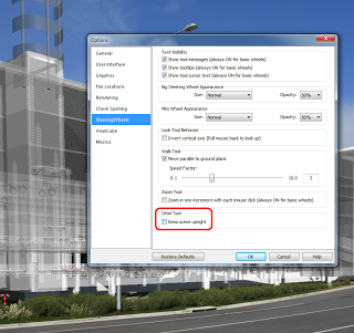
- Use Orbit for final fine tuning – you can drop the Centre point, then Rewind and it will remember that as the Orbit centroid. Drop it on a known point and Orbit. You can turn off Keep Scene Upright in Steering Wheel settings. With a SpacePilot, just turn on all your axis and slowly and carefully match the view.
From here, you can use Render Settings and set the image as a background with “Stretch”.
Also, for each camera position you can have one 3D view set for “camera matching”, and one set up for rendering, and to align one to the other use ViewCube “Orient to View”.
Overall, it can still be a tricky process. The 3D mouse makes it much easier – you can basically just rotate, zoom, pan until it looks about right. Remember to select a couple of “known” objects in the model, this will allow better control when using the 3D mouse…
There are other more geometric methods available for Camera Matching too:
What Revit Wants: How to match a Revit 3D view to a real life Camera Photo
