Coming from an AutoCAD background, it comes as second nature to me to draft bounds (boundaries) in AutoCAD. Set your Units to Deg/Min/Sec, set north to 0 degrees and use Clockwise, then start typing and use the @ symbol to start the new line at the current location. Its logical and reliable. In Australia, we generally have all our survey reduced to that form – 0 degrees for North, then Clockwise bearings related to that.
Here is my experience with using Revit Property Lines as they were intended (?) to be used…
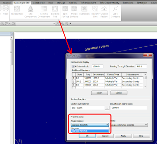
First step is to enable the Degrees from N/S setting in your Site Settings:
Then, go to a Plan View and set it to True North. Start the Property Line tool and select Create by Entering Distances and Bearings.
Ok, basically you enter the length, the angle, and choose either N/S and E/W. That’s it. But what settings should you choose?
You always need to reduce your bearing dimension to something between 0 and 90 degrees (the dialog will not accept anything outside of this). You can do this using a formula, like:
=180-140° 00′ 35″
Then you use the N/S and E/W switch to mirror or flip the dimension bearing. In some cases, it is easier just to hit OK and see which way it is heading, then switch between the N/S and E/W settings till it looks right. If it still doesn’t work, you may need to orient it inversely against 90 degrees, by doing something like:
=90-0° 44′ 10″
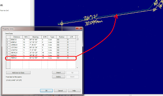
Let’s do an example. Here is the Property Line segment we want to make:
We can’t use 261 degrees, so we use a formula to minus 180 from that angle. Then, as my previous line was using S and W, I set those to the new line. It works! Here is what it looks like:
You can see that my line is slightly off the background image – this will be fixed once the whole boundary has been input (it can be moved at that point).
To reduce the above unit entry process into a simple step-by-step:
- Using an inplace formula, subtract 90,180 or 270 from the bearing to make it less than 90.
- Choose a quadrant into which the line will protrude from a given starting point -NE,SE,SW,NW
- If the line still does not match, subtract the bearing from 90 to correct it (flip within the target quadrant).
Good things about Revit Property Lines based on tables:
- You can quickly check the data
- Data can be changed relatively easily
- Closing line can be added
Bad things:
- Can be slow and repetitive
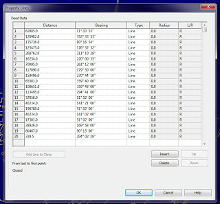
Interestingly, once you have created your Property Line, you can turn off the NS/EW setting in Site Settings, and when you Edit the Table, it will show all boundaries related to True North:
Further reading:
Property Lines by Distances & Bearings missing N/S and E/W – The Revit Clinic
Revit Architecture 2010 User’s Guide: Creating Property Lines with Survey Data
RevitCity.com | Property Lines


