subtitle: Most Revit hacks ever in one blog post??
Have you ever faced flex duct modelling problems in Revit? Revit fails to generate these in some cases, usually when the spline becomes too tight for the geometry engine to handle.
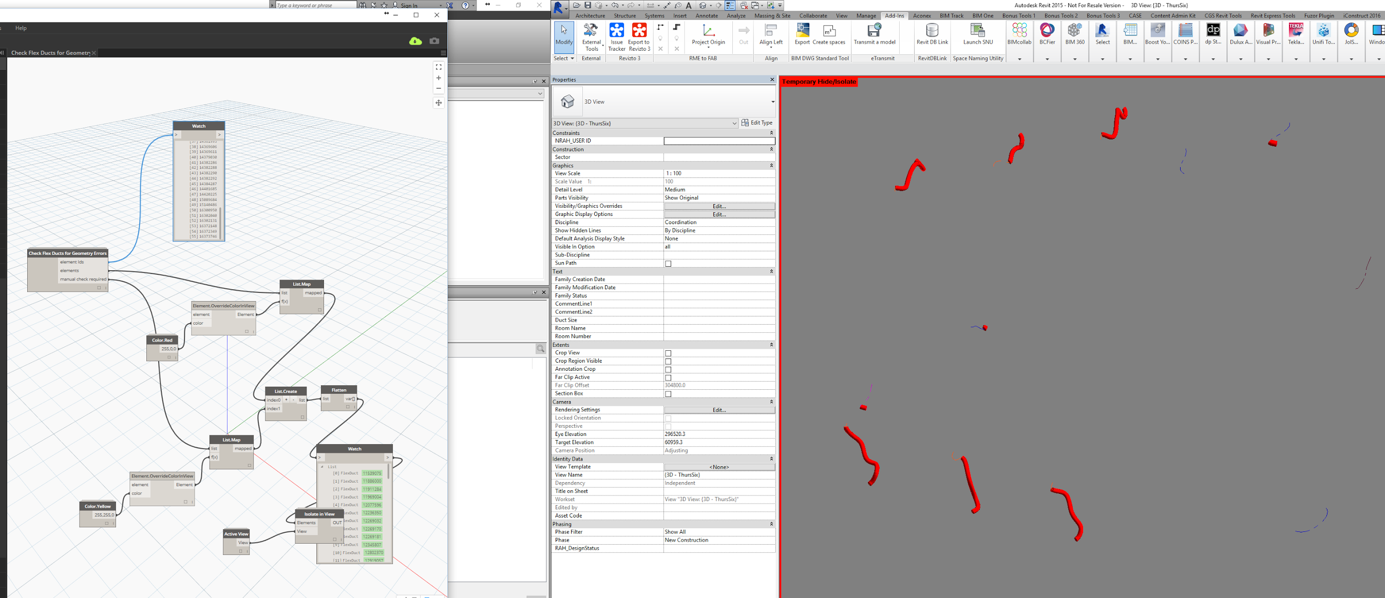
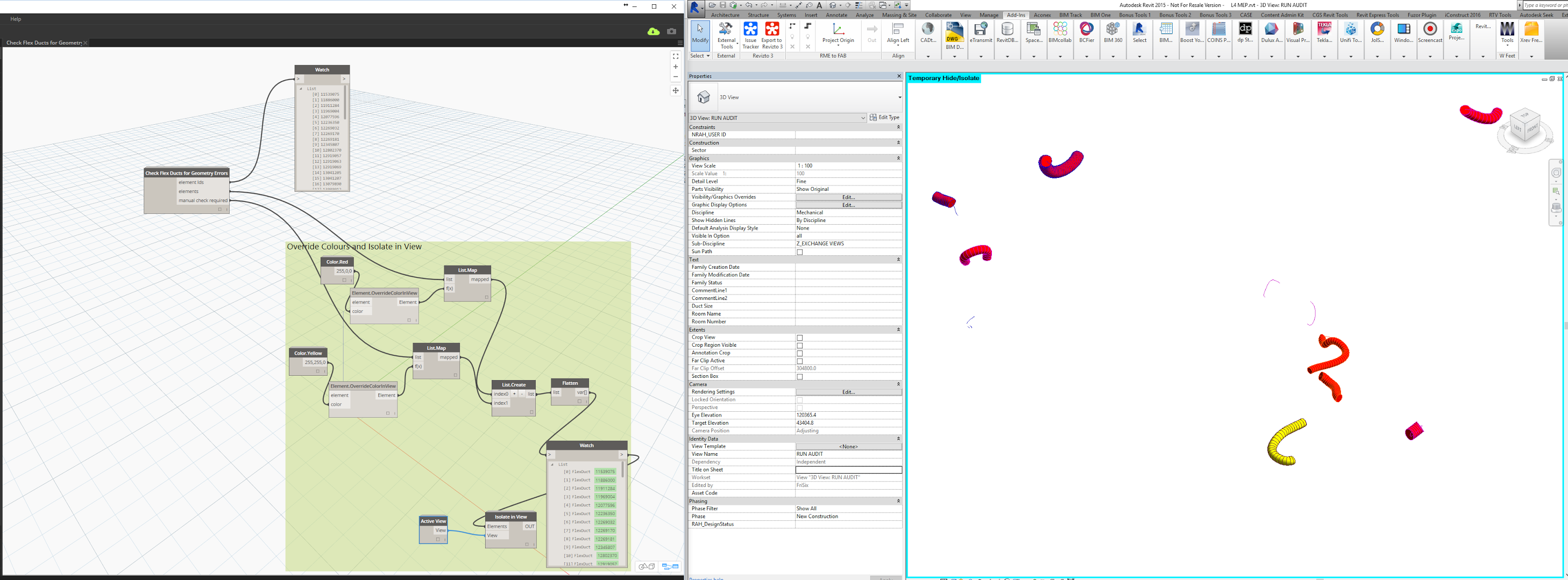
- Collects a list of flex ducts in the current model
- Checks their 3D geometry against what it should be (using a Volume calculation)
- Reports a list of problem element ids
- Overrides these elements to red in the current view
- Isolate the elements in the Current View
It looks something like this:
So first of all, we need to get the driving points from the Revit MEP element, so that we can start playing with curves. At the same time, we should get start and end tangents, and Diameter too. I created this node in Python for this task:
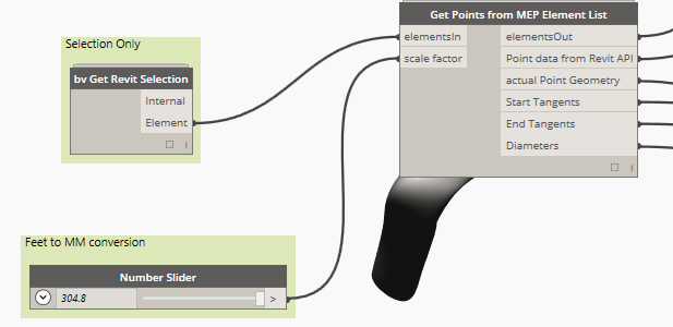
You can see that I have added conversion input here, because the units coming out of the API were a little weird (back to the old feet units thing). Ok, now that we have points, we have to regenerate the driving curve and then play around with it a bit… it looks a bit like this:
You will notice I try both Nurbs and Polycurves, because sometimes either will fail. Using both seems to be pretty reliable.
Then, with some nice Nurbs curves in hand, we have to try and make some circular-ish sweeps along them. I actually sampled a number of circle profiles by 3 points, and used nurbs surface UV degree of 3, as this seemed to be the most ‘reliable’ form creation for strange paths. However, even this still failed occasionally, so I created some ‘backup’ forms (using only start and end circle profiles), and then I rolled them all together into one (hopefully) reliable ‘no nulls’ list:
Now we can basically take a set of Flex Duct elements (where Revit is failing to generate the right geometry), and smooth out and generate our own Flex Duct ‘form’ in Dynamo. From there, we have a few options to get it back into Revit:
- ye olde but pretty reliable ImportInstance.ByGeometry or .ByGeometries
- Dynamo 0.9 users can go with DirectShape
- you could try beta Spring Nodes FamilyInstance.ByGeometry (thanks to Dimitar Venkov)
- we can also use Mesh Toolkit to convert to Mesh, make Watertight, and export to file..
I wanted the most ‘Revit’ solution, because after all, this blog is about What Revit Wants! So for me, that was trying to get these forms into a family on the right category. First problem: there is no Flex Duct Family Template available, because that just isn’t allowed… so I had to make one using the IFC roundtrip (with custom IFC mapping files), then saving inplace to a component family, and renaming to RFT.
Now, with the Geometries in one hand, the Flex Duct Family Template in the other, and a wrapper node to run FamilyInstance.ByGeometry once per geometry, let’s see what happens!
Well, initial results from running the node weren’t great, but I noticed that the families were getting generated in the 3D View in Revit, and then disappearing… so I went to Revit and pressed ‘Undo’ and all my nice new Flex Duct Families re-appeared!
Screencast:
Want to give it a try yourself? Here’s how to use the dyn:
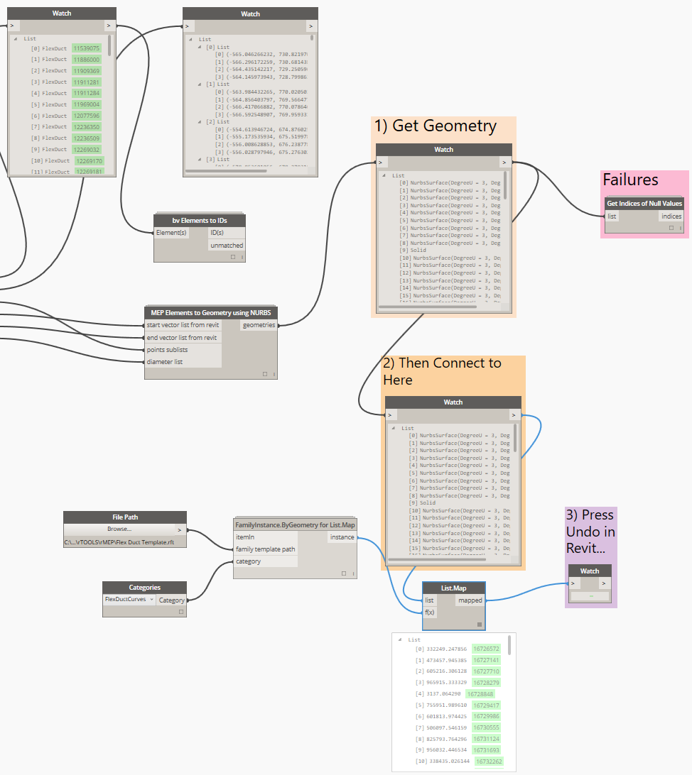
- Go to a 3D view and select some Flex Ducts
- Open Dynamo, and the definition from link below, and press Run. Confirm there are no ‘failures‘…
- This should collect list of Geometry
- Connect the two orange boxes, 1) and 2)
- Press Run again
- This should have made families for you, using a random number as the family name
- Press Undo in Revit to make the families ‘reappear’
- Close Dynamo and save your project
- You may need to open individual families and set the Subcategory to something new so that you can override colours and materials in the Project.
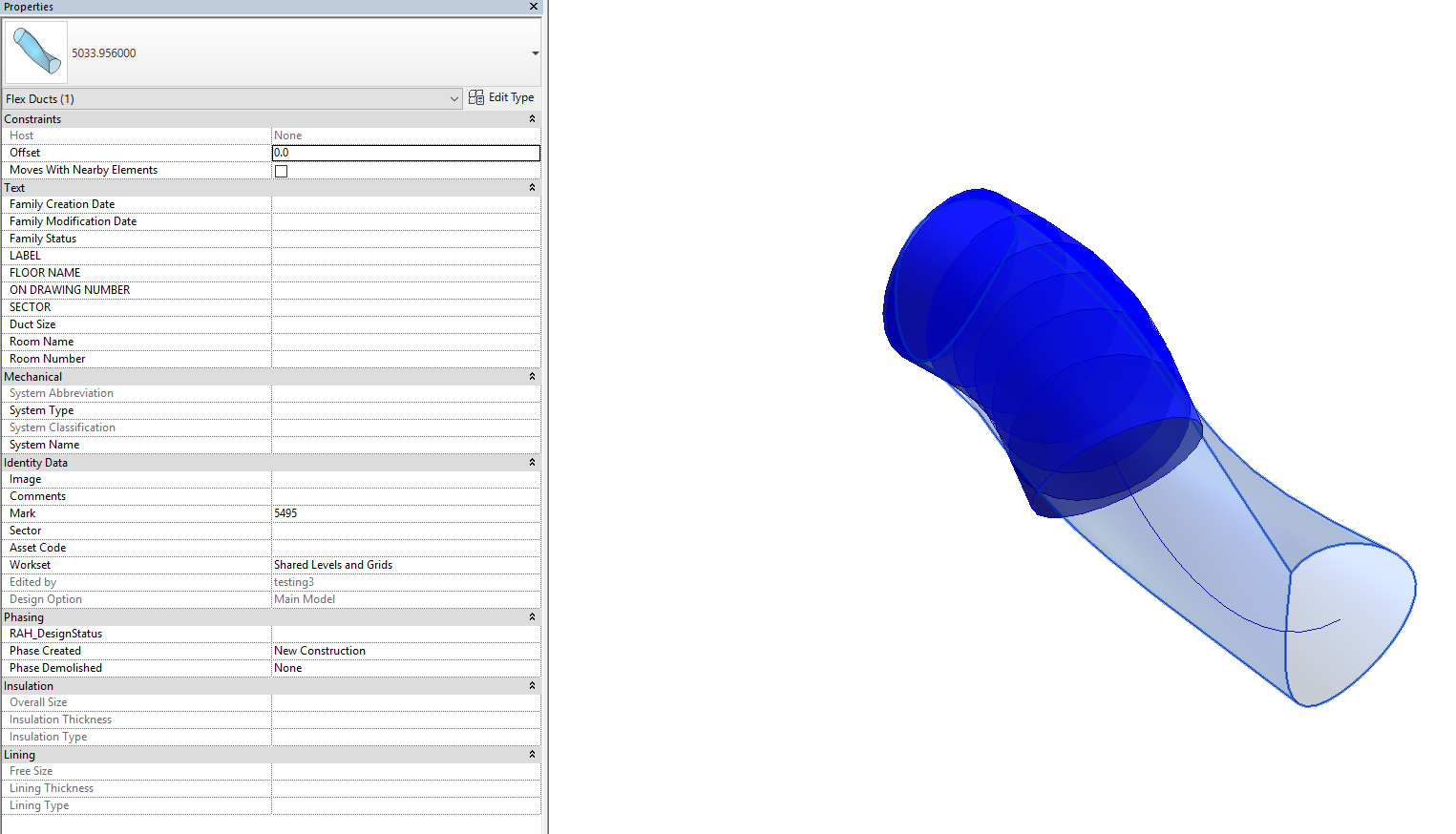
Here’s one instance in the project:
This is the main definition:
This is the project browser list of families:
Needless to say, this workflow comes with as many disclaimers as possible, because we are:
- using Dynamo before v1 (0.8.2 in my case)
- using hacked family templates to
- make component families on categories they shouldn’t exist on with
- a beta custom node and then
- working around some weird issues by pressing Undo after running Dynamo
- etc 🙂
You will need Bakery package (version from around 9 December 2015, and its dependencies) to get all this working. Here are some other required resources for download:
Flex Duct family template and main Dynamo definition
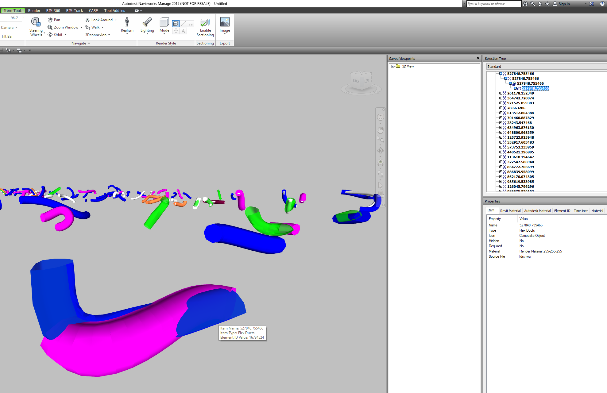
Exporting these families using Navisworks exporter seemed to work ok, as shown here:
Other Prototype Imagery:
