It requires no installation and allows you to selectively switch Revit addins on and off prior to launching Revit. Obviously, this is easier than manually renaming .addin files, and quicker than uninstalling / re-installing addins all the time 🙂
Interestingly, the Bitbucket site is under BoostYourBIM, so it looks like Harry Mattison (probably the best Revit API coder in the world) was involved in building this helpful little tool.
Here are the steps to install (copied from the original post):
Find where you downloaded the zip file and unzip it.
When unzipped, there will be a BIN folder; browse into the BIN folder then the Debug sub-folder.
Run the tool by double-clicking on the exe file.
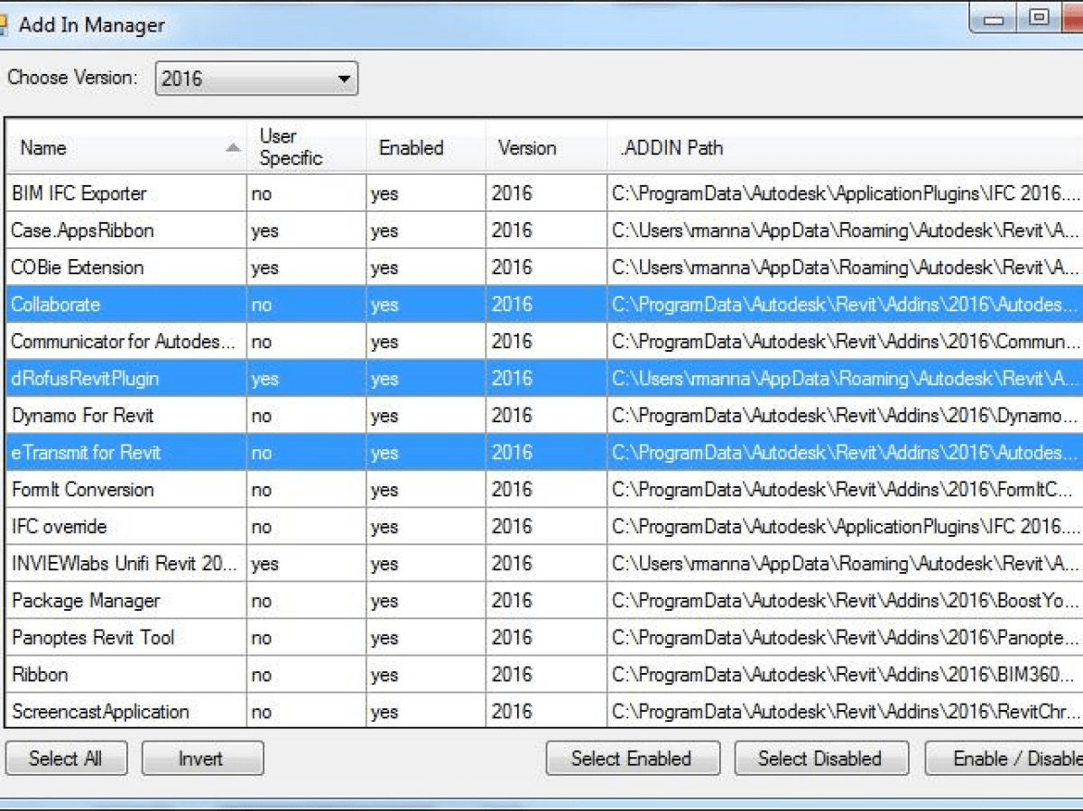
In the window that opens, pick your version of Revit (or go with all if you like).
The data grid will update to display all of the machine wide and the logged in user specific add-ins installed. You can pick and choose, invert, select all, then simply click on the “Enable/Disable” button to either enable or disable the selected add-ins.
Once you’ve made your choices, start Revit in the normal manner. Simple and easy.
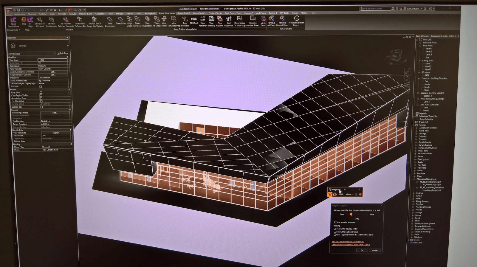
Manufacturers are really starting to get on board with Revit and create some interesting tools, like this one from SALDA. Basically, it connects their AHU selection software with a Revit addin that builds or updates the AHU families automatically.
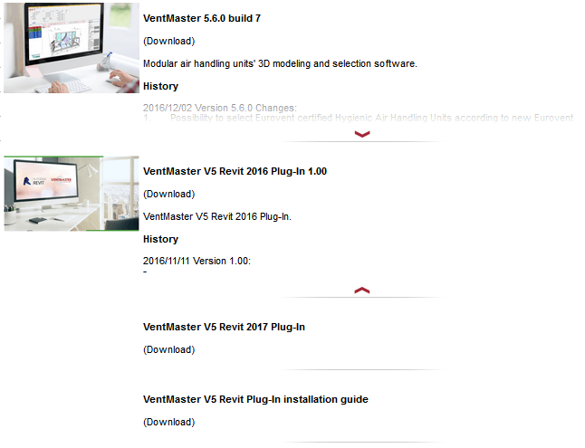
VentMaster V5 Revit Plug-In
is a tool that allows Autodesk Revit users to insert Air Handling Units (Exhaust AHU, Supply AHU, Heat recovery AHU and AHU with heat recovery coil) after their selection in the main AHU selection software. Software automatically creates Air Handling Units and imports all the necessary design information into Autodesk Revit. All needed parameters are visible for regular Autodesk Revit users. Software allows users to update the families after changes have been made in the model.
The main functions:
Design is a funny thing. The word itself carries a certain weight, it is somehow deliberate and exciting at the same time. Yet, so often design is let down by the poor translation or communication of ideas. You may have an excellent ‘design’ in your mind, but displaying or presenting that to a client is an entirely different matter. Every designer faces the same challenge of communicating their design ideas in a thoroughly engaging way: whether the communication be to their clients, other stakeholders or even as part of their own internal design process.
This is a site about Revit, but this article is about discovering new possibilities, new ways to express your design, new ways to add context, realism and reality. It is also about a powerful piece of software called Lumion– a design communication tool that I personally use and have used for quite a few years. Thecombination of Revit and Lumion give architects a complete toolkit for modeling, understanding, sharing, adjusting and presenting their design.
So, what is Lumion? Recently, I was speaking to the Chief Operating Officer of Act–3D, (the parent company of Lumion), Roger Hammond. He told a me a very heartening story about the development of this piece of software…
Often we don’t immediately recognise the full potential of a new, beautiful idea. Roger describes that Lumion was initially designed to be a powerful presentation tool, but Architects soon discovered that it can also shift the way they design in very positive ways. He describes how a new user of Lumion can easily get comfortable with the basic concepts of the software, even those who are not ‘technical’ or especially comfortable with computers. Yet, once they start using Lumion, they get to grips with it easily and quickly learn to iterate design changes and brief clients more rapidly and smoothly. Lumion gives a certain realism and context to your design that can assist you to modify and improve the design internally, before it is even time to present it to anyone.
We often become so used to a way of working that we almost feel like there is no other way, or that perhaps we already have the best way. Yet, if that were true, innovation would not be a reality. Sometime, disruption is necessary. So if you have an established way of designing and communicating, take this opportunity to re–evaluate as I reviewLumion.
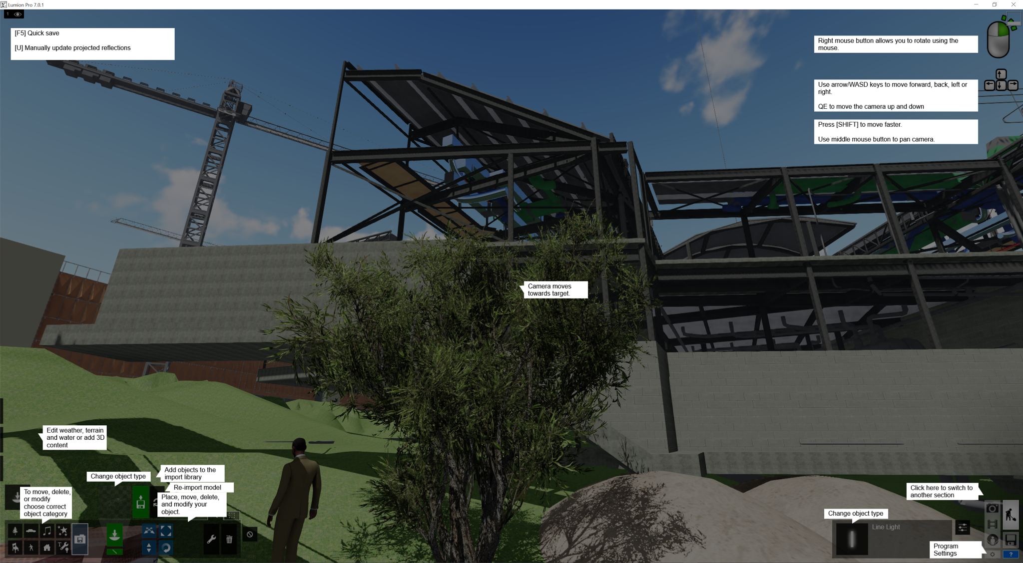
The user interface itself is nice and clean and easy to read and understand. As someone used to complicated programs like Revit and AutoCAD, this is a welcome breath of fresh air to me. Rather than present you with an overwhelming and detailed set of buttons, Lumion allows you to progress your digital presentation in stages, from Building to Materials and Lighting and Presenting and so on.
Lumion – A User Interface For Designers
In this way, the development of your design and your presentation output can be very logical and layered. You can import your design from a variety of different programs and platforms (like Sketchup and ArchiCAD, not just Revit), and once imported you can add people, trees, and soft and hard landscaping. You can sculpt the site topography and add water and grass areas. Once you feelcomfortable, you can dig deeper, modify lighting, adjust materials, add special effects, work on camera angles…
And finally, you can display your design in some truly simple yet beautiful and intuitive ways. The key thing is not to be afraid. You can’t break things in Lumion, it is not a imposing or complicated environment. Navigation is straightforward, nothing is very complicated. As you use it, extra functionality will reveal itself. It is a tool that has been built for designers, and its development has been shaped by their feedback. Roger recalls that it is not uncommon for users to say that “Lumion has changed my business”, and there are plenty of ‘wow’ moments. For example you can add the ocean to your scene with just one click…
We have experienced this realisation at Virtual Built. Recently, we have been demonstrating Virtual Reality tools to our clients. However, in some programs it can be difficult to populate a scene quickly and then output to a suitable VR platform. This is not the case in Lumion, as the included content means you can get up–and–running quickly. If you have a few basic building models, you can add site context and a few nice little details like a truck or a crane to create a site utilisation model, and then output to a number of different VR panoramic formats.
I have been using Lumion over a number of years and different versions, so I was excited to see theupdates and new features available in Lumion7. The major new features are listed below, and we will dig into each feature and uncover the new opportunities they present.
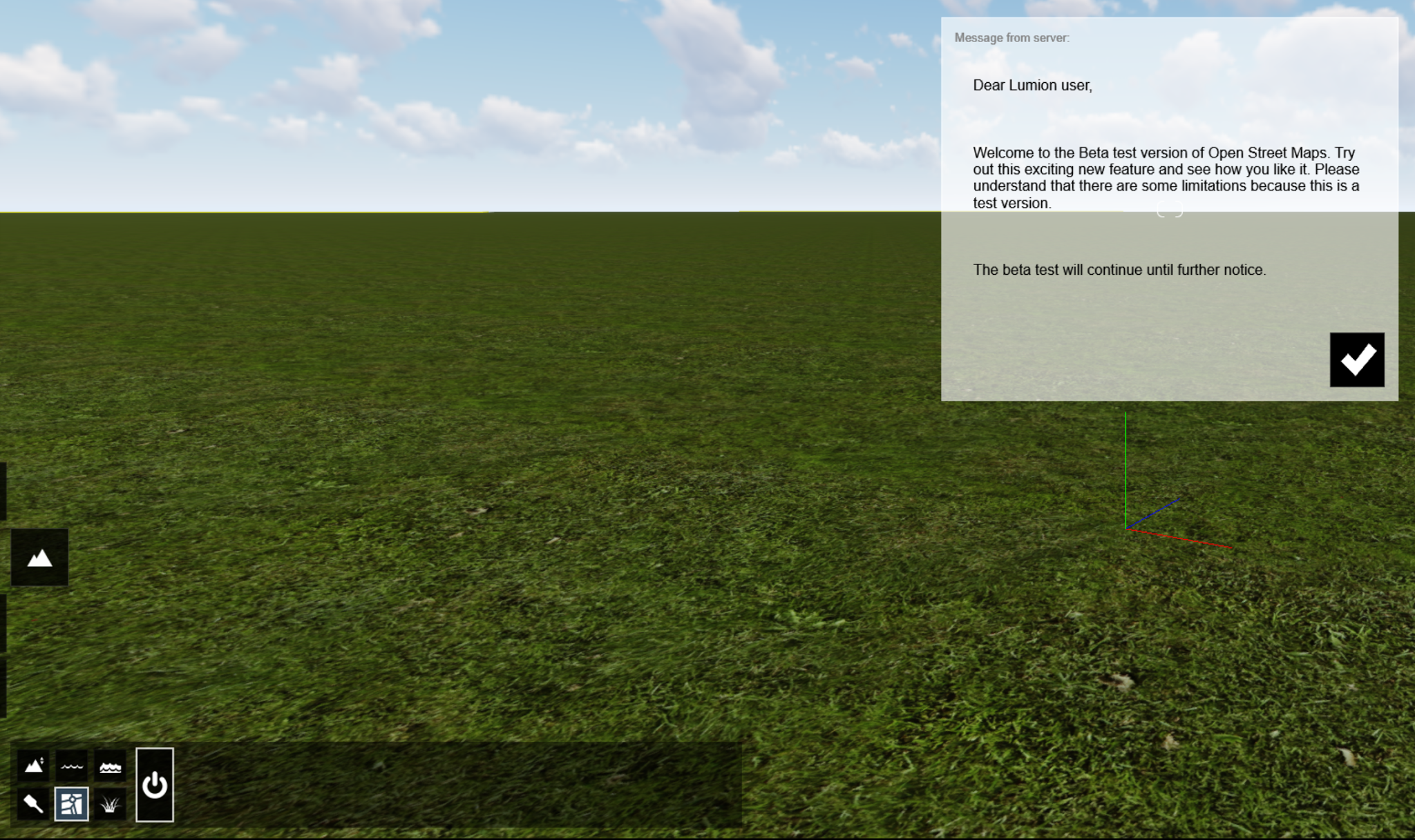
Lumion7 New Features OpenStreetMap (OSM) is an online resource that stores 3D building models along with map information like roads and water areas. In the past, I have used many methods to try to get a locality plan or model created, and it can be quite clunky and challenging. However, in Lumion7, this is now completely automated. Using the OpenStreetMap import, in just a few minutes you can have a realistic map in Lumion to locate your building models, and it will even have adjacent 3D building models as well! It will automatically ‘cut out’ your own building model from the OSM data. The OSM function in Lumion7 is still Beta functionality, but it can already be very useful to quickly add context or a background to your design.
To get started with OSM in Lumion, just:
Start Landscape mode (left side flyout menu) and turn the OSM switch ‘On’
OpenStreetMap Switch
Click the Longitude / Latitude area to bring up a searchable map
Search for your location
Location Search
Set the import Range and press Download
Tip: hold Shift + Spacebar and use arrow keys to move quickly on large sites
Check out this page for more information on OpenStreetMap and Lumion.
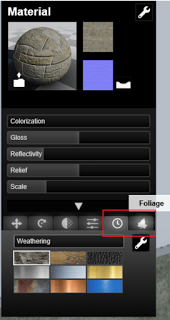
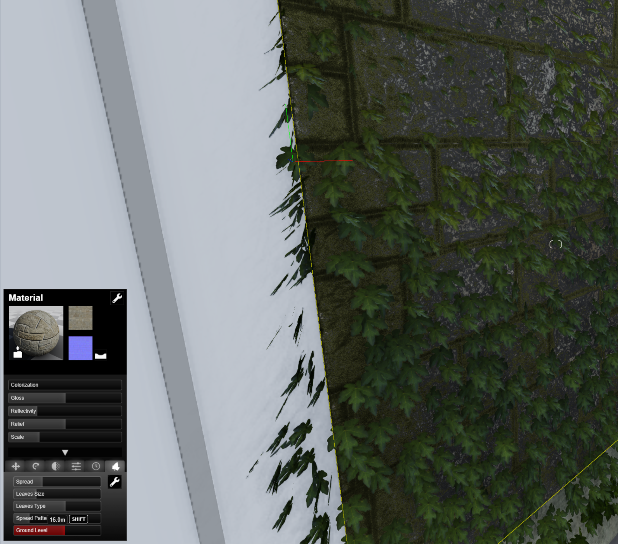
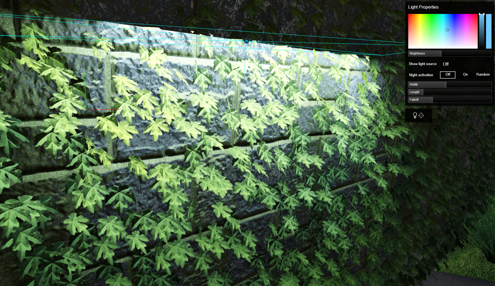
New Features for Weathering and Foliage
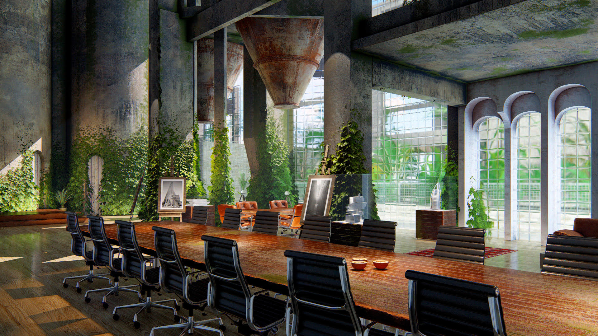
Building models sometimes appear ‘flat’ due to the way various platforms handle materials. However, in Lumion7 you can now remove the coldness of computer–generated imagery by seeking out edges, roughness and other properties of natural materials to make them look like they’ve been around a while. My associate here at Virtual Built, Michael Clothier, recently used this to add realism to an important theatre building in Adelaide that is currently under construction.
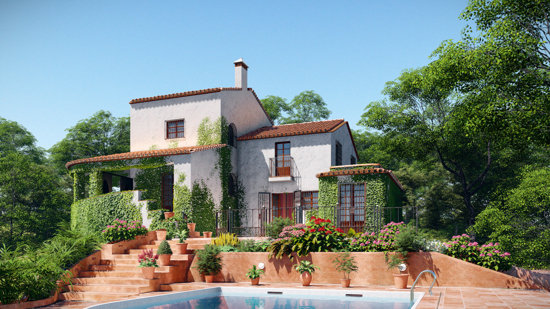
You can also cover models with leaves or add weathering, ageing and transparency. Even transform any object into thousands of leaves or add ivy to a wall… These tools are implemented through the Material Editor, so the workflow is logical but the effect is quite impressive indeed.
Here are some examples:
Boardroom
Pool Villa
To get started with these tools:
Enter the Material editor
Select a object to change
Set a Material from theLumion Library, and double–click on it
In the editing pane, you will find the tools on the right…
Then, simply drag the sliders until you have the desired look and feel
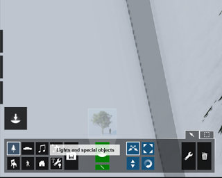
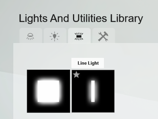
Light strips
Sometimes, the available Lighting tools in presentation software can be quite limiting. Happily, in Lumion7 you can now add light strips or area lighting, meaning you can go beyond simply ‘spot lights’. I really enjoy adding these new lights, because as usual they can be edited with sliders, and you can view theeffect in real–time… there is no need to wait for a lengthy rendering and then realise the lights were switched off 🙂
To get started with the new Light types, open the Object pane:
Then select the Area Lights tab:
Place the light and then modify the sliders until you have the desired effect:
MyLumion
You can use Lumion to share a navigable panorama to anyone who owns a smartphone. It is incredibly simple and powerful and is one of the features I hinted at earlier in the article. It is something that allows you to put your design on display in a new way, and get valuable client feedback and engagement. Then, you can quickly iterate the design and send them a new link.
We have used this to create sets of views for various stakeholders, but the key thing is really how easy and quick it is. You don’t have to print something or even save an image and find it on your hard disk. You can do all of this creation and sharing in just a few clicks. We have found it to be a real game–changer.
Summary There is no software program available that can automatically interpret a client’s design brief, provide suitable visualisations, interpret client feedback, and iterate this process while learning at each step. A good Designer can do this. But with the right tools, parts of that process become much easier. As a designer, you will be able to interpret the brief and interpret client feedback. With Lumion, you can quickly and easily present your design, in context, and in a multitude of rich, realistic, immersive ways. By thus improving the way you communicate and iterate your designs, you designs themselves will improve. And your client satisfaction level will soar…
So I recommend that you give Lumion a try. And be ready to be surprised 🙂
Guide 1: Using Lumion in Virtual Reality Workflows Lumion VR Lumion VR viewer is no longer supported, instead you can render static images for viewing on a variety of VR platforms. I will provide some notes on how you can do this below.
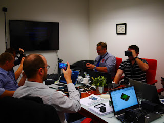
Using A Mobile App like PlainVR
Here’s how:
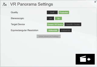
Render VR Panorama images (these will be 360 degree jpg files). You can use default 64mm eye to eye and 360 slices
Photo:Virtual Built Pty Ltd using Lumion VR to PlainVR for builders in a Revit training session
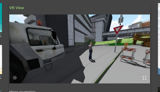
Embedding VR to a Website with VR View
Google has kindly provided a web service for rendering images in VR, its called VR View. After creating your stereoscopic image, you can follow these steps to embed it into your site:
Note: in Blogger, after you add an ampersand character to the code, it converts it to some other characters. basically, you can’t ‘edit’ after you input the code, if you publish it directly it won’t replace to & and it works…
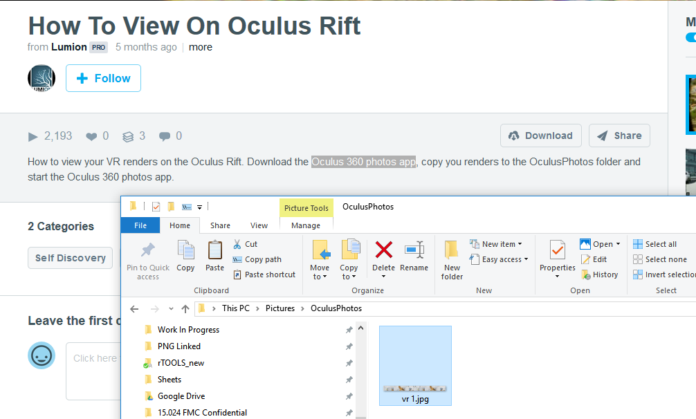
Using Oculus with Lumion
To do this:
Render a 360 jpg file from Lumionthen
View it in a panorama viewing app, such as Oculus Photos
Guide 3: Installation and Links
If you would like to get started using Lumion, here are some steps to get you started quickly:
Verify your computer Click here to see if your PC is suitable for Lumion Click here to see the general system requirements for Lumion. Click here to install the latest graphics card software and all available Windows updates.
Get the download manager
You will get a special email that lets you download the software… Lumion7 Viewer will be released later. An update e–mail with download information will be sent as soon as the viewer is released
Download Lumion
Double–click on the Download Manager to run it.
Follow the instructions to install Lumion. Click here if you have any problems.
Register your license
You can register your License Key to a forum account.
You can now get technical support on theLumion Support Forum
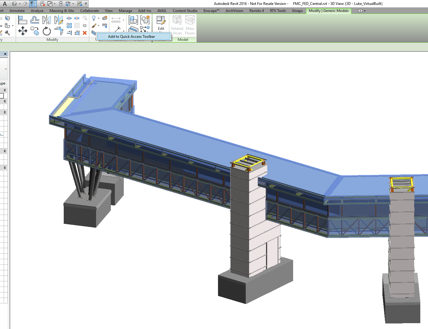
Selection Box is a new tool in Revit 2016 that allows you to quickly crop a 3D section box around selected elements (without installing any addins). However, it doesn’t always show up on the contextual ribbon. For example, if you are editing a family in-place… the tool doesn’t seem to be available.
However, we can work around this problem by simply adding the Selection Box tool to the Quick Access Toolbar.
Select any object
When you see the Selection Box tool in the ribbon, right-click on it and ‘Add to Quick Access Toolbar’
Now, in various other modes in Revit, the tool will still be available 🙂
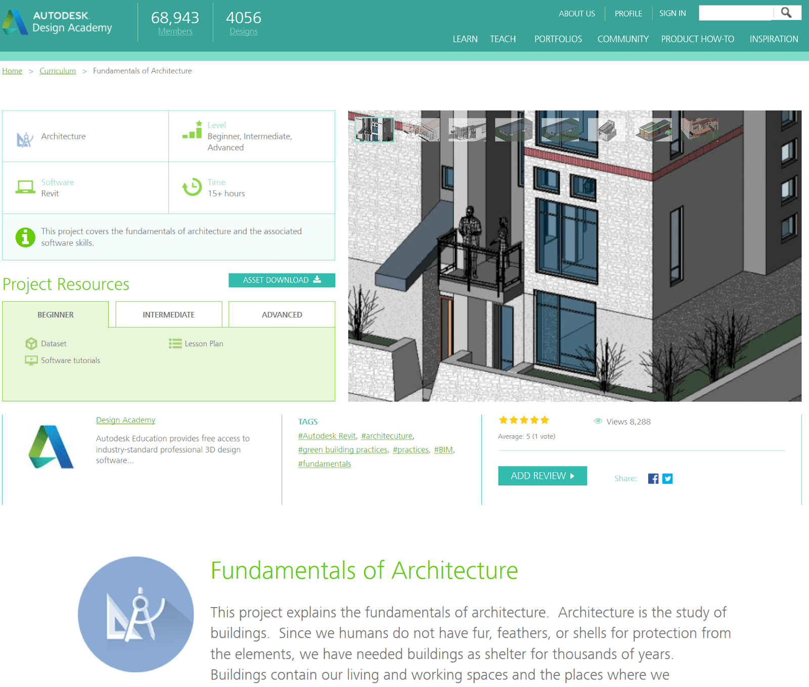
This site usually focuses on intermediate to advanced workflows and topics, but here I just wanted to mention a couple of getting started resources that you may find useful. There is a new and comprehensive video playlist on the BIMscape channel, and I have embedded it here:
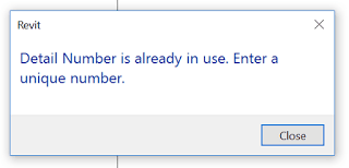
Revit Wants you to have a unique Detail Number for each Viewport placed on a Sheet. This makes total sense, and allows you to trace from a Referencing View, through a View Tag (telling you which Sheet and Detail Number that View is on), and back again… The Viewport knows which Detail Number it is, and which Sheet is referenced from.
Ok, that is What Revit Wants. And in fact, it doesn’t allow you to have duplicateDetail Numbers,
… because that would be madness, right? Well, in some Architectural firms, they may have drafting standards which indicate something like this:
We will reference Interior Elevations from our General Arrangement Floor Plan
The View Tags will have letters a, b, c, d and so on for each Room
These Interior Elevation views will be placed together on Sheets
We will append the Room number to the Detail Number so that we can figure out which Elevation a is which…
Meaning that there will be multiple Detail Numbers that could be the same on each Interior Elevation Sheet
I’m not going to speak to the validity (?) of this logic, but lets just say sometimes drafting standards from past ways of doing things don’t mix so well with Revit. How do we work around this problem?
I’m not so proud of this, but it is one of those hacks that just seems to work…
Create the Viewport Title Tag with a Shared Parameter for the View Room Number, and the Detail number in one label together
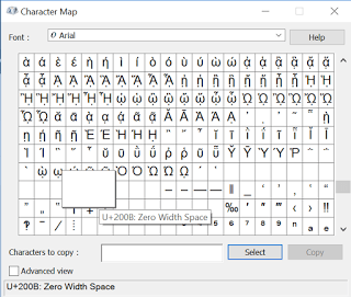
Use a special invisible character to make the Revit program think the Detail Number is different, when it appears exactly the same to human eyes… as I said this is bad Revit
How do you do step 2? Just copy one of these characters from your Character Map and paste it after the Detail Number that Revit doesn’t want you to have. So you type ‘a’, then press Ctrl+V to paste the special character in to the Detail Number parameter:
This is the Unicode character U+200B: Zero Width Space.
Oh, and have you ever wanted to get rid of that annoying question mark in a Revit Tag because there is no value? Just put in one of these Zero Width Space characters and it will go away 😉
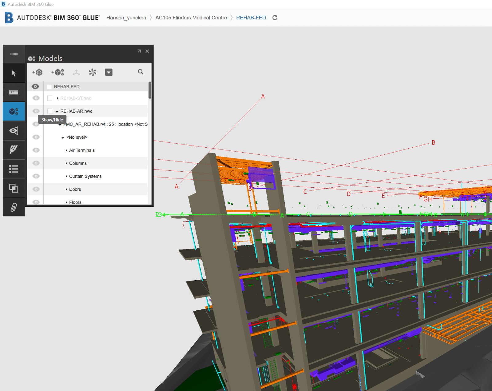
Recently I had an issue sharing colour overrides from Navisworks to BIM 360 Glue. This has been ok for a while, but something broke. After some investigation, it turns out that one of the sub-Models in the Glue merged model was causing the problem.
I typically convert IFCs using the Link method, which results in DirectShape objects. It seems that one of the Architectural files that I converted this way from ArchiCAD to Revit and then to BIM 360 Glue was stopping the colours from getting baked into the BIM 360 Shared View.
To workaround this issue:
Determine what problem model/s you have (possibly those converted from IFC)
Open your Merged Model in Navisworks for BIM360
Hide these problem models in Navisworks scene
Run Appearance Profiler or otherwise apply colour overrides
In the BIM 360 Shared Views pane, click New to make a new Shared View on BIM 360 Glue with the colours ‘baked in’
Go to Glue desktop app and confirm the colours are working
Then, Unhide the problem model here…
And then make a new view in the desktop app
This new view should have all models you want showing, and the colour overrides working ok.
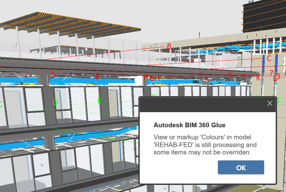
On a related note, you may have seen this warning:
View in model is still processing and some items may not be overridden
It seems that this might put your Glue merged model in a dirty state? Try deleting all views with this message before trying to create Shared Views from Navisworks with colour overrides.
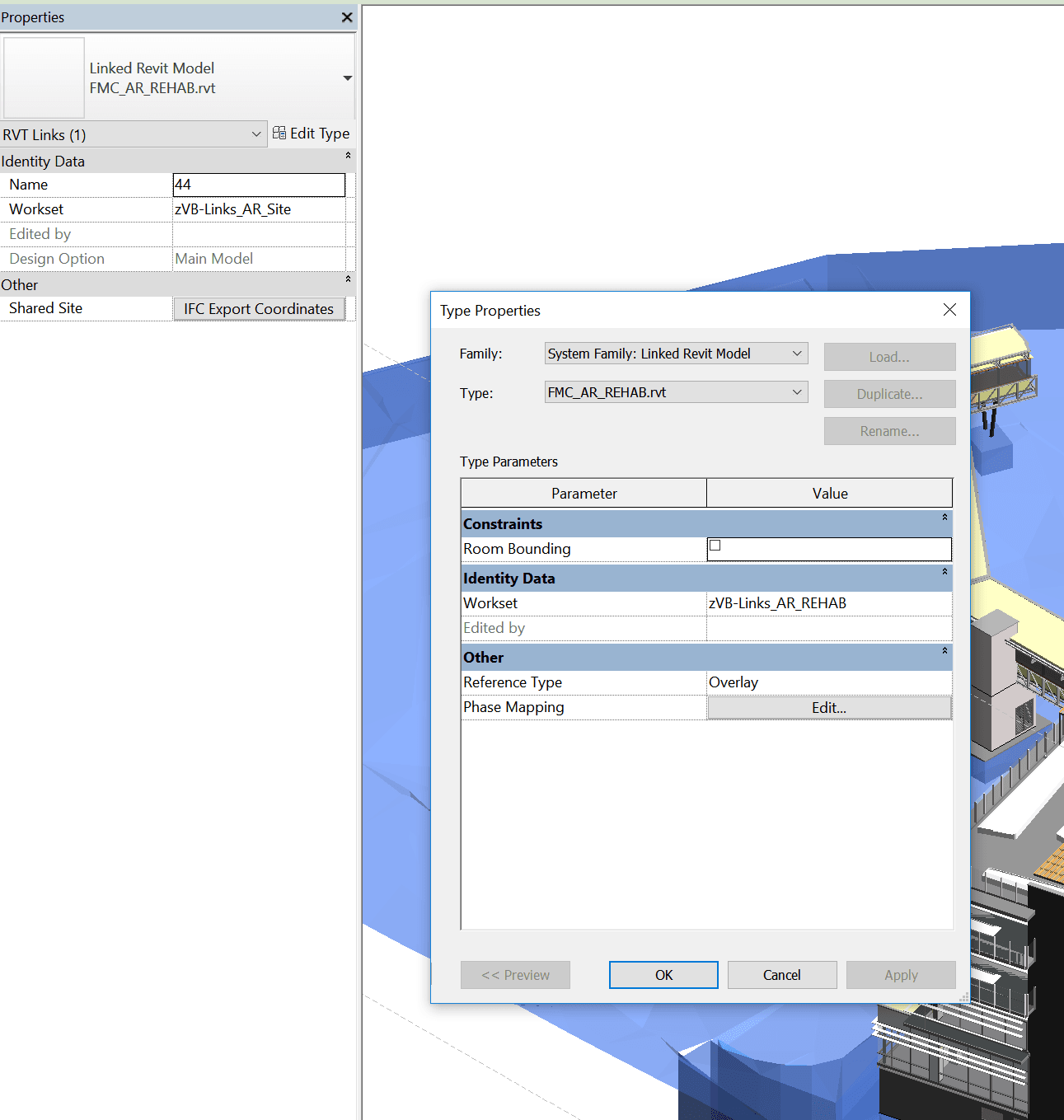
In Revit, each Link is bound to both a Type and an Instance. So you can have one Link ‘Type’ – relating to a single RVT file that is linked into the project. But it can be placed multiple times in the project, thus having multiple instances. In workshared projects, the Type and the Instance can belong to different Worksets.
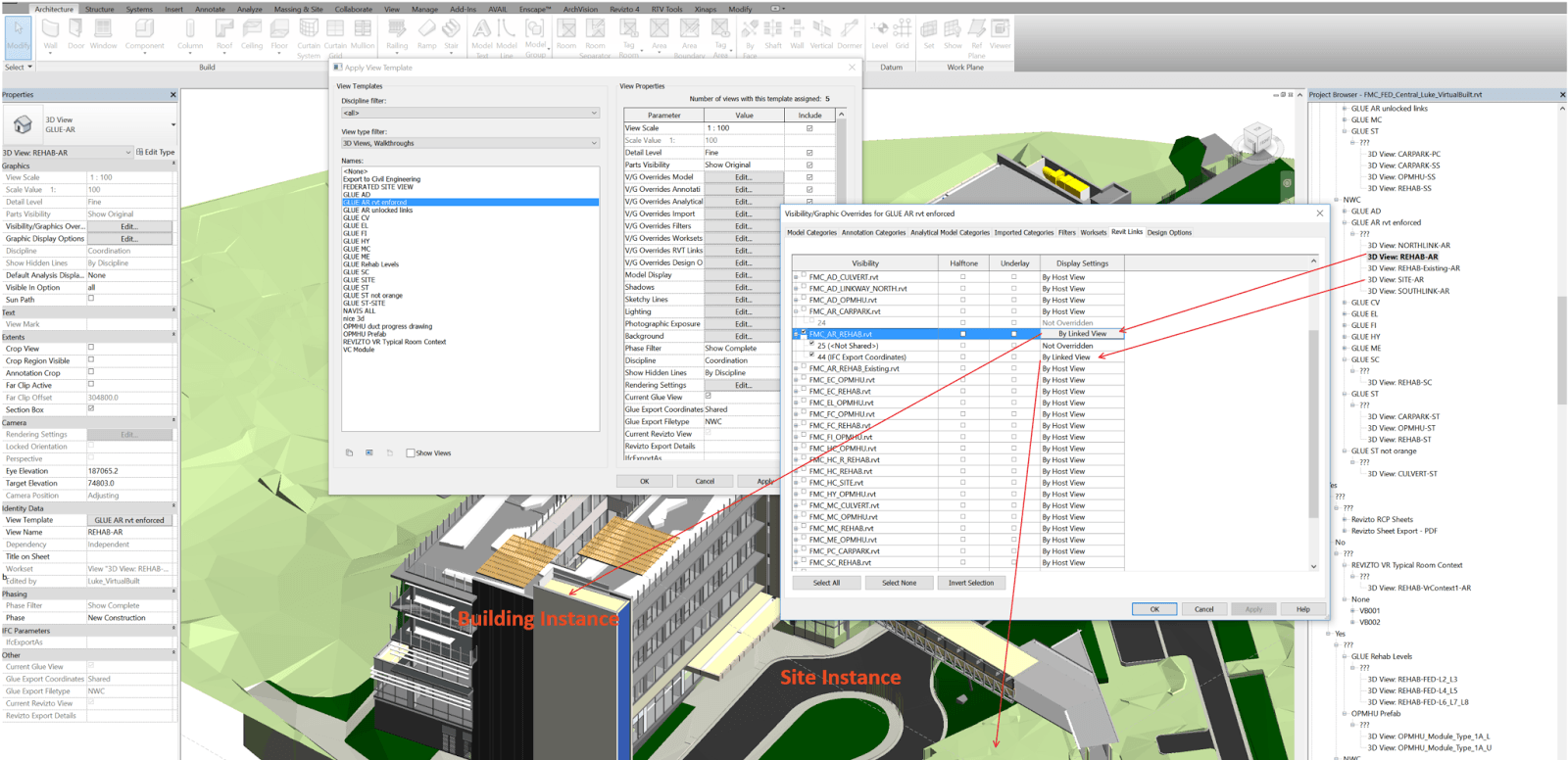
Did you know you can use Linked Views to display two identical copies of the same linked model in different ways?
To add control, you should create 3 worksets – 1 for the Type, and 1 for each Instance, as shown below:
Then, set up two different Linked Views in that linked model. In this particular case, I want to use a model converted from ArchiCAD to a single Revit file. But I want to be able to separately load and display the Site objects, and the Building objects. So I have an Link Instance for each, and linked views for each. The whole rig can be seen in the image below.
Using the worksets, I can separately Load / Unload each Instance (closing a Workset unloads any Link instances on that Workset from memory). And using the Linked Views and Overrides for the Instance, I can display each instance as I like. I can also load both instances and show both in a ‘combined’ view.
Final note: Link Instances can be located in different positions in the Host model, and they can have different Shared Coordinates. Using the methods above, you have a lot of flexibility to be able to use a single linked Revit model in many different ways…