Here’s how it works:

There’s not much of an interface for this one, you simply go to a sheet
and run the command.  It will then go into a selection mode asking you
to “Pick viewports in the desired order.”

Download Viewport Renumber 2013, 11.48 kB

Download Viewport Renumber 2014, 11.92 kB

Original post by Tim Logan:

Revit Viewport Renumber Tool | LMNts

There is a nice selection of AU2013 videos embedded into a recent post on Form Follows Performance, starting with:

AB2947: Applying Open Standards and Levels of Development (LOD) to Building Information Modeling (BIM)
Follow this link for details and materials download:
http://au.autodesk.com/au-online/classes-on-demand/class-catalog/2013/revit-for-architects/ab2947

Check out the full list at:
BIM & Performative Design Learning Classes from AU2013 Now available online | Form Follows Performance

I worked with a Structural Engineer recently who used to model Void Forms in his Structural Columns so that he could “cut” them into walls and other geometry.

However, this created a bit of an issue when the Structural model was linked into the Architectural – namely, orange voids would occasionally show up, because they were not cutting anything.  Obviously, this type of scenario is not ideal, but it is actually quite common to come across modelling practices that associates or other companies use that don’t really fit directly into your own workflow. In those situations, you often need to find a workaround, or perhaps discuss this issue to try and come to a compromise.

In this case, the engineer recommended this course of action:
I just noticed some of the columns have the yellow voids displaying, this is a Revit gremlin that creeps in overtime and needs to be fixed every few days or before issuing but I forgot. I can fix it and re send alternatively if you have started working with the file, it is as simple as editing the family changing a parameter and reloading It, essentially doing a regen. The other option is to select all rectangular columns and change the parameter ‘void offset’ to say 2.

How do you deal with differing modelling practices?  Have you been able to solve these issues, or have they become permanent headaches?  At Virtual Built, it is our primary goal to make teams function more efficiently throughout the entire BIM process.  Do you have a problem that needs solving?  Or do you have a great workflow solution that you would like to share?  Feel free to contact us.  Let’s collaborate!

http://bit.ly/MuT5fT

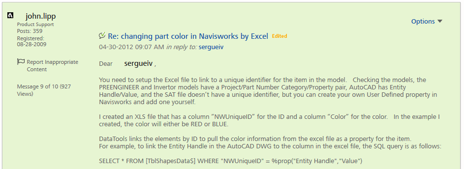
This forum post by John Lipp is definitely worth a read:
http://forums.autodesk.com/t5/Navisworks-General/changing-part-color-in-Navisworks-by-Excel/m-p/3437673#M3555

In part:
Then repeat for the other datatools links changing the Category for COLORS_proengineer, COLORS_INVENTOR, and COLORS_User Data.

Then after the profiles are set up, you can click Run in the appearance profiler, and the colors will change according to color properties that are being pulled from the excel file.

I’ve attached the Excel file, Appearance Profiles dat file to import, and the NWF with the datatools links setup.  If you drop the three files in the folder with your models, open the NWF, import the .DAT file into the appearance profiler tool and run it, it should change the items in the models to either red or blue based off of the colors specified in the excel file.

This example has colors specified in the excel file, but you could use some other property in the database such as “Out of Service” column with a value of either yes or no and create an appearance profile that checks if that property is yes, and if so, set the color of those items red.

With the appearance profiler, you need to actively run the appearance profiler to set the colors if the excel file is updated.  If you wanted more automation, then you may wish to look into the Navisworks API.

Attachments: