This topic is somewhat of a work in progress (I know Julien and a few others have been chasing how to make this happen nicely).  Lev Lipkin made a comment on the thread, which reads a bit like a how-to, but to my knowledge it is probably more of a wishlist at this stage.

First, a few basics for setup:

  1. Install Vasari Beta 3
  2. Open / activate Vasari
  3. Install Dynamo (experimental builds here).  If you want to try DynamoDS, here is the current download.  (Remember all that talk about Dynamo and DesignScript merging?  DynamoDS seems to be where its happening…)
  4. Packages – Search for a Package
  5. Install relevant packages / nodes and…

Then, have a read of this:
Comment here

Quoted below:

Permalink Reply by Lev Lipkin
Dynamo when working on Vasari beta 3 has node “Face From Points” (which needs n x m grid of points) and “Replace Solid Faces” (which would keep adjacent faces as bounds of the resulting Solid). Resulting solid could be put into Form using “Bake Solid as Revit Element” node. Hope this might help.

EDIT The merging of DesignScript and Dynamo was confirmed by Ian Keough:

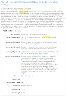
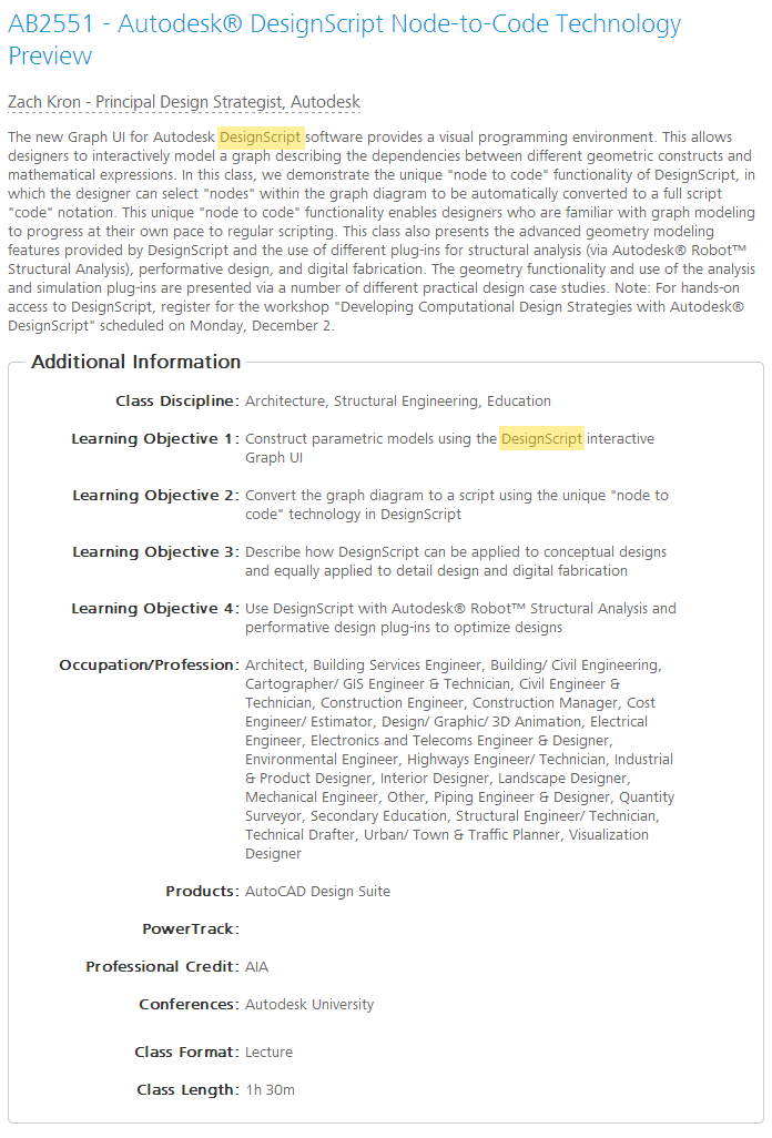
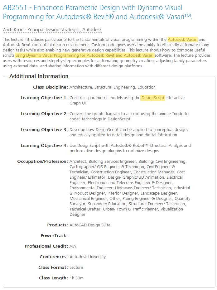
There is some interesting “fluidity” of language in discussing DesignScript, Dynamo, Revit and Vasari in the following two class descriptions of AB2551…  I guess all will be revealed at the AU class on Thursday, Dec 5, 8:00 AM – 9:30 AM.

From this:
snapshot of the page as it appeared on 22 Oct 2013 12:40:35 GMT

To this:
1 Nov 2013

via
Enhanced Parametric Design with Dynamo Visual Programming for Autodesk® Revit® and Autodesk® Vasari™.

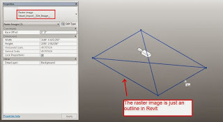
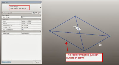
Most of you probably know that you can use a Decal in a 3D view set to Realistic for 3D masterplanning.  The annoying part is that you have to somehow scale the Decal properly.

You may also know that Vasari has a nice built-in method of grabbing Google Earth imagery and unlike Revit, Vasari is happy to show this image in 3D views.

Now, Philip Chan has combined these two methods to make a decent workflow for Revit:

  1. Grab the image in Vasari first
  2. Open that Vasari file in Revit
  3. Import the same image from Vasari into Revit as a Decal and place it on a flat workplane
  4. Use the “borders” of the Vasari image to properly scale the Revit decal
Its a bit fiddly, but until Revit supports images in 3D views, it will have to do.  Or, you could convert the image to a DWG and use that (I’m mostly kidding).

In Philip’s words:
use a trick to get it scale properly. I actually used the Vasari file that I made earlier, I drew some model lines at the boundary of the image, copy the model lines to the clipboard, and then paste them into my site file. Now that I had the actual size of the boundary, I could use the same image export from Vasari and placed it as a decal.

Read the whole post:

Check it out at:
Vasari Beta 3 Download

New Features page
(text copied below the line)

Heads-up from Village BIM

  • Windows 8 support. Now, in addition to the other platforms that Vasariis supported on, Vasari is also supported on Windows 8.
  • Arc by point sketching. You can now select the Start-End-Radius Arc tool to sketch an arc by point curve in your massing project. See Drawing Overview.
  • UV grid alignment. You can use the Align tool to align the UV grid on a planar divided surface by using a straight edge of the surface as a reference, or an external reference. See Aligning UV Grids to a Reference.
  • Non-rectangular crop regions and callouts. Now you can change a rectangular crop region or callout view to a non-rectangular shape. See Editing a Crop Region. You can also create non-rectangular callout views.
  • Materials: Enhancements to the Material Browser dialog include the following. See Materials.
    • The Material Editor functionality has been integrated into the Material Browser dialog. To edit a material, select it in the Material Browser, and edit information in the tabs in the right pane, now referred to as the Material Editor panel.
    • You can now assign, sort, and organize materials by class.
    • When displaying a project material in the Material Browser, the hand icon  displays in the right pane of the Appearance, Physical, and Thermal tabs indicating how many materials in the current project share the same asset. If the hand displays a zero, the asset is not shared (used) by any other materials in the current project. The asset is only used by the currently selected material.
    • The ShowHide Library button has been added to the project material pane. This lets you collapse the library panel if you need to display more items in the project materials list. See About Material Libraries.
    • The Material Parameters dialog is now modeless, so you can view and change custom material parameters more quickly. Specifying Custom Parameters.
  • Schedules:The following enhancements improve the look and function of schedules:
  • Schedule formatting and layout: The following formatting tools are now available for schedules. See Modifying Schedules.
    • Grid view formatting: You can now apply column shading, borders, and font overrides. Insert and delete rows or swap parameters from the ribbon. Precision sizing of rows and columns is also available.
    • Format Units tool: You can now open the Format Units dialog from the ribbon.
    • Calculated Values tool: You can now open the Calculated Values dialog from the ribbon.
    • Clear Cell tool: You can select and clear the contents of multiple title cells from the ribbon.
    • Formatting visibility: Formatting now displays on sheets and is available to print from a sheet view.
    • Column indexes: You can now quickly select entire columns using the indexes at the top of each column.
    • Schedule title formatting: You can now insert rows to the title area and apply the new grid view enhancements. You can also merge cells. Additional formatting includes adding images, project parameters, and plain text.
    • Text types: You now specify title, header, and body text styles by selecting a system text type. See Formatting a Schedule.
  • Displace elements: Available in any 3D view, including perspective, this tool helps you create displaced views. The new Highlight Displacement Sets tool on the View Control Bar highlights the elements that have been displaced. SeeCreating a Displaced View.
  • Alternate dimension units: You can display alternate dimension units along with the primary units for all permanent and spot dimension types. This feature allows you to simultaneously display both imperial and metric values in drawings. To use alternate dimension units for a specific dimension type, such as Aligned, modify the type properties for the Aligned dimension type. See Defining Alternate Dimension Units.
  • Segmented elevation view: You can now split elevations into segments that are orthogonal to the view direction just as you can for sections. See Segmented Views.
  • Change sort order of multiple detail items: You can now select multiple detail items or imported raster images, and use the Send to Back, Send Backward, Bring to Front, or Bring Forward tools to move them all in one operation. See.
  • Print option for masking regions: A new print option allows you to determine whether the edges of masking regions and filled regions cover other lines. See Print Setup.
  • Double-click editing options: Double-clicking a parameter, such as a parameter value displayed in a room tag, now consistently allows you to edit the parameter. Also, new user interface options allow you to configure the double-click behavior to edit the following elements (see User Interface Options):
    • families
    • sketch-based elements
    • views and schedules on sheets (activate view)
    • groups
    • component stairs
  • Dockable windows: The following windows can be moved and resized, and either floated or docked:
    • Project Browser
    • Properties palette
    • Reconcile Hosting window
    They can also be grouped so that several windows (represented by tabs) occupy the same space on the screen. See Dockable Windows.
  • Selection enhancements: New options allow you to determine whether you can select link elements, underlay elements, pinned elements, and elements by face in a model. You can set the Drag Elements on Selection option so you can move an element without selecting it first. You may want to disable these options when having trouble selecting a particular element in the model, or to avoid inadvertently selecting or moving elements. See Controlling the Selection of Elements.
  • Data from lookup tables is now stored within the family, eliminating the need for external CSV files: Use the Manage Lookup Tables tool while editing a family to import, export, or delete lookup table data. See Managing Lookup Tables.
  • Temporary View Properties: You can now temporarily apply a view template from the View Control Bar. See Selecting a Temporary View Template.
  • Textures, line patterns, line weights, and text are now included in 3D DWF exports.
  • DWG/DXF export: The following layer standards for exporting DWG and DXF files have been updated to reflect the latest changes. See About Exporting to CAD Formats.
    • American Institute of Architects (AIA)
    • ISO standard 13567
    • Singapore standard 83
    • British standard 1192
  • Imported forms: When an imported instance containing 3D solid geometry is exploded in the Family Editor environment, the 3D solids are now preserved. Each 3D solid becomes a free form element, which can be used for cutting, joining, and other form operations. These free form elements can be edited by dragging the shape handles on planar faces. See Exploding Imported Geometry.
  • Optimized view navigation: A new feature on the Options dialog boosts performance by disabling some graphic effects when you are navigating a view. To learn more, see Optimized View Navigation.
  • Online Help: Vasari online Help is no longer hosted on the Autodesk WikiHelp platform. Now Vasari online Help is hosted on the new Autodesk Help platform which has a new look and feel.