I hinted that this was coming a few weeks back, but now here it is! A massive Subscription Release, along with a giveaway of the Siteworks addin package to Subscription users.

Download the update at: Autodesk Revit 2015 R2
Download the Siteworks package at: Autodesk Site Designer Extension for Revit 2015, or on Exchange here
(Note: you will need to login to your subscription account to access these) 

A few quick tips…
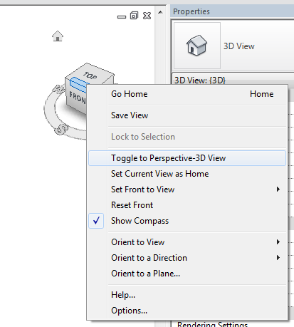
To toggle between Perspective and Orthographic view:

  1. Go to a 3D view
  2. Turn on Crop View
  3. Turn on Show Crop Region
  4. Right-click Viewcube
  5. Select Toggle to… and this will show Perspective or Parallel depending on your current mode


If you are wondering what ‘quick adjustments’ you can do in Perspective views:
Basically, you can use some simple commands like Align and Move, that were previously grayed out in Perspective mode.

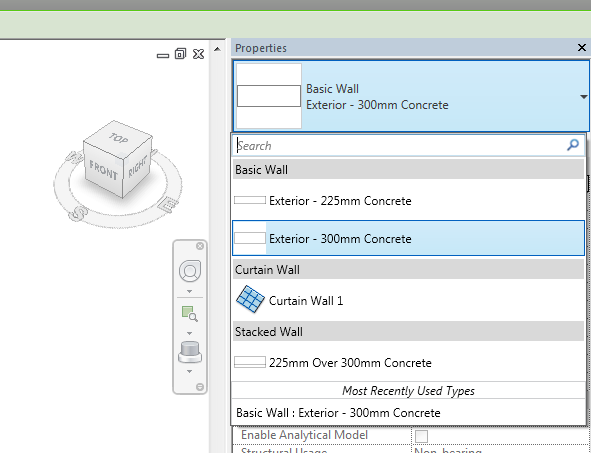
To search in the Type Selector:

  1. Turn on Properties pane
  2. Click in the top of the Type Selector
  3. The search box is the top row

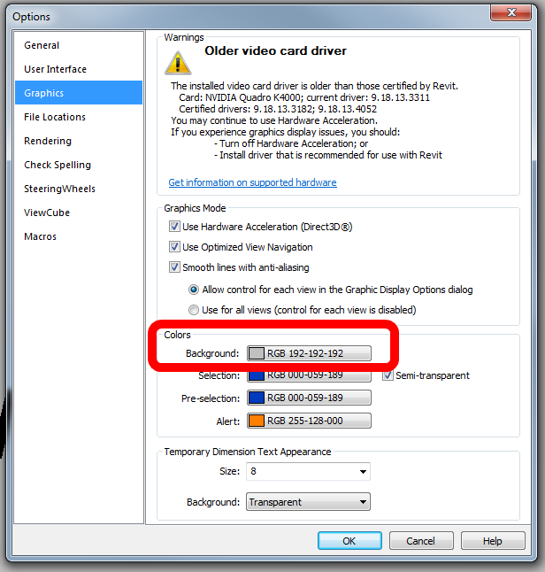
You can now also set a custom background colour (that means ‘color’ to U.S. folks):

 
Enhancements list:
http://revit.downloads.autodesk.com/download/2015RVT_RTM/R2/Enhancements_List_RVT_2015_R2.pdf

Readme (Interesting point: The install of Autodesk Revit 2015 Release 2 will also install Autodesk Dynamo (0.7.1) and required component IronPython.)

My top 3 features in Revit 2015 R2:

  • Work in perspective views, making quick adjustments without having to change views with some modeling capabilities now available in perspective views.
  • Find content more quickly with Search capabilities in the Type Selector and all drop-down lists.
  • Navigate PDFs exported from Revit more quickly with hyperlinked views.

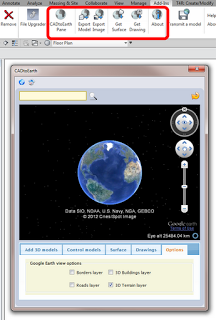
My top 3 features in Autodesk Site Designer (previously Eagle Point Siteworks):

  • More quickly add design elements to your site such as berms and drainage swales, minimizing the time required to mass grade a site and to try alternatives at the design development stage.
  • Special terrain families within Site Designer provide you with parameters that control widths, cut and fill slopes and other projection settings.
  • Locate hardscape components such as streets, intersections, sidewalks, curbs and walls that can follow the existing terrain and have controlled elevations and slopes – all while the toposurface is automatically maintained.

More info:
Autodesk Revit 2015 Subscribers Get Slew of New Capabilities with “R2” Update

Heads-up:
Revit 2015 R2 Release | Applying Technology to Architecture

A few notes on installation versions from the Readme:
This update requires either the initial release of Autodesk Revit 2015 (build: 20140223_1515) or Autodesk Revit 2015 Update Release 3 (build: 20140606_1530) . Autodesk Revit 2015 Update Release 3 will need to be applied to any installed Revit 2015 which has either Autodesk Revit 2015 Update Release 1 (build: 20140322_1515) or Autodesk Revit 2015 Update Release 2 (build: 20140323_1530) applied. Installation will also be blocked if Autodesk Revit 2015 Update Release 4 (build: 20140903_1530)) has been applied, a full uninstall followed by a new install of Autodesk Revit 2015 will be needed in order to apply Release 2.  

Coming from an AutoCAD background, it comes as second nature to me to draft bounds (boundaries) in AutoCAD.  Set your Units to Deg/Min/Sec, set north to 0 degrees and use Clockwise, then start typing and use the @ symbol to start the new line at the current location.  Its logical and reliable.  In Australia, we generally have all our survey reduced to that form – 0 degrees for North, then Clockwise bearings related to that.

Here is my experience with using Revit Property Lines as they were intended (?) to be used…

First step is to enable the Degrees from N/S setting in your Site Settings:

Then, go to a Plan View and set it to True North.  Start the Property Line tool and select Create by Entering Distances and Bearings.

Ok, basically you enter the length, the angle, and choose either N/S and E/W.  That’s it.  But what settings should you choose?

You always need to reduce your bearing dimension to something between 0 and 90 degrees (the dialog will not accept anything outside of this).  You can do this using a formula, like:

=180-140° 00′ 35″

Then you use the N/S and E/W switch to mirror or flip the dimension bearing.  In some cases, it is easier just to hit OK and see which way it is heading, then switch between the N/S and E/W settings till it looks right.  If it still doesn’t work, you may need to orient it inversely against 90 degrees, by doing something like:

=90-0° 44′ 10″

Let’s do an example.  Here is the Property Line segment we want to make:

We can’t use 261 degrees, so we use a formula to minus 180 from that angle.  Then, as my previous line was using S and W, I set those to the new line.  It works!  Here is what it looks like:

You can see that my line is slightly off the background image – this will be fixed once the whole boundary has been input (it can be moved at that point).

To reduce the above unit entry process into a simple step-by-step:

  1. Using an inplace formula, subtract 90,180 or 270 from the bearing to make it less than 90.
  2. Choose a quadrant into which the line will protrude from a given starting point -NE,SE,SW,NW
  3. If the line still does not match, subtract the bearing from 90 to correct it (flip within the target quadrant).

Good things about Revit Property Lines based on tables:

  • You can quickly check the data
  • Data can be changed relatively easily
  • Closing line can be added

Bad things:

  • Can be slow and repetitive

Interestingly, once you have created your Property Line, you can turn off the NS/EW setting in Site Settings, and when you Edit the Table, it will show all boundaries related to True North:

Further reading:
Property Lines by Distances & Bearings missing N/S and E/W – The Revit Clinic

Revit Architecture 2010 User’s Guide: Creating Property Lines with Survey Data

RevitCity.com | Property Lines

One of the greatest things about Revit, and BIM in general, is that we usually design ‘in context’ – that is, with as much site information as we can get our hands on…

Vasari has that handy little option to import a Google Earth image into your model – well now, Revit has an add-in that does a bit more, including:

  • import surface from Google Earth
  • upload building to Google Earth

It is called:
CADtoEarth | Autodesk Revit | Autodesk Exchange Apps

Here is a quick guide on importing topography from Google Earth:

  1. Close Revit
  2. Install the tool from above link
  3. Start Revit
  4. Click the CADtoEarth Pane button
  5. Use the search box at top of the dialog to find your site
  6. Zoom in until the ‘can’t save’ message disappears
  7. Click the Surface tab in the dialog and click  Save Earth’s Surface
  8. Leave the dialog open, and click the Get Surface button on the Revit add-ins Ribbon panel
  9. Your surface has now been added to the Revit file as a Import Symbol.
  10. Use the Topography tool if you want to create a proper Revit topo from the imported data

Heads-up:
http://revitaddons.blogspot.com.au/2012/08/cadtoearth.html

From their website:

CADtoEarth is a family of innovative add-in applications for the most popular CAD packages that link modeling environment with Google Earth and Microsoft Virtual Earth.
CADtoEarth offers some very exciting capabilities. Here is the partial list of what you can expect from the tool:
  • Upload a model directly from modeling session onto Google Earth or Microsoft Virtual Earth
  • Import a section of the surface of the Earth directly from Google Earth into modeling session
  • Position your 3D structure on the imported surface within modeling session and then upload it back to Google Earth or Microsoft Virtual Earth
  • Perform the same operations on 2D objects in modeling environment and Google Maps
At the moment you can download CADtoEarth for the following platforms: SolidWorks, Autodesk Revit and Autodesk Inventor.
Please, take a look at the video demonstrations of CADtoEarth below. Those will give you a good idea about what this tool can do for you today and what you may want to see changed or added to fit your specific needs. So, if you would like to customize or enhance this generic tool to better fit you company guidelines then we’ll be more than happy to discuss the requirements with you.

CADtoEarth | amcbridge.com/

(embedded JWPlayer)

In Revit, you can’t use the linework tool on the physical edge of a Toposurface.  Worse still, the edge has no distinct category of its own.

The only viable workaround that lets you consistently hide the edge of a Toposurface is to change its Object Style color to white.  You can still set you Primary and Secondary contours to show in black or whatever color you use.

This method creates its own problems – like if you draw a grey filled region over the edge of the Toposurface, the ‘white’ line may show through and print.  In any case, feel free to ask Autodesk for some better visibility control over Toposurface elements.

While you are at it, why not ask for Toposurfaces to comprehend phasing properly?

Tip via:
AUGI – View Single Post – Linework tool w/ Topography