Including:
- image read
- excel read and write
- family by points
- working with SATs
- Python
What Revit Wants

Including:
From a LinkedIn discussion:
normal .ifc file from Tekla with the rebar option ticked and imported it into MicroStation, from there I exported a .sat file of the rebar and inserted it into Revit. Of course this means you can’t modify it in anyway but if all you need it for is to cut sections then works quite well.
via
Precast modeling export to Revit | LinkedIn
This can be done with AutoCAD MEP 2015, or Architecture, or similar verticals that have the IFCEXPORT command.
The advantage of doing this over importing the SAT directly to a Generic Model family is that the IFC method will result in individual forms for each bit of the SAT file. If there are 1200 forms, you will get 1200 families in Revit. This, in turn, will export to Navisworks with this level of element hierarchy (instead of just one big imported SAT element).
This will also result in higher granularity of clashes when using the converted SAT via IFC method (more forms to clash against).
You probably know that you can attempt to explode a SAT in a Revit family, but I find that sometimes unsupported elements disappear using this method… so I like my way via AutoCAD a bit better at this stage.
I have previously discussed going from Navisworks to Revit using FBX – 3dsMax – SAT. However, maybe we can do this without 3dsMax. Did you know that vanilla AutoCAD has a FBXIMPORT command?
1) Export FBX from Navisworks – it will ignore Section clipping planes, but it will respect the Hide/Required setting of the view. You can limit polygons (advised for big models)
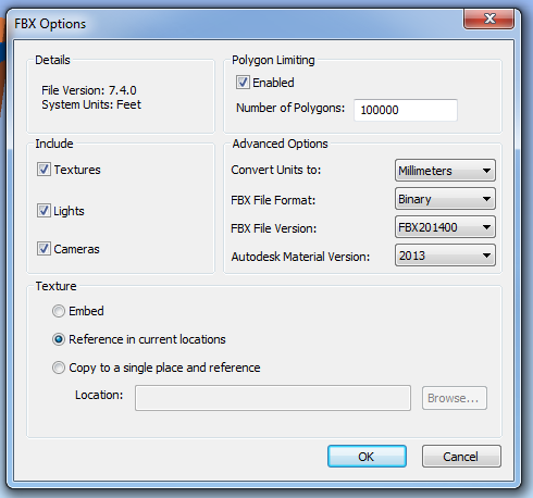
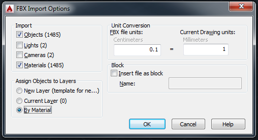
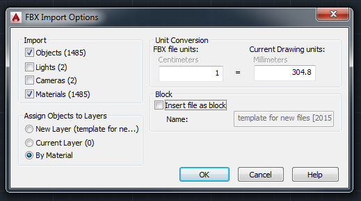
2) FBXIMPORT in AutoCAD – untick Cameras and Block options as they can be problematic.
Then save DWG. (Note – see below for correct 1:304.8 import scale)
EDIT: If using Navisworks 2015 FBX export to version 2014, with Advanced Options units set to millimeters, you can import to AutoCAD 2015 with 1:1 scale factor (using latest service packs)
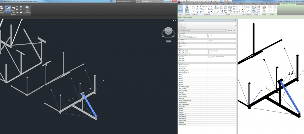
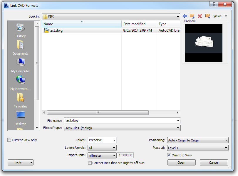
3) Open Revit and Link in the DWG.
For this example, I used Origin to Origin as I wanted to try round-tripping back to Navisworks.
Once I exported the NWC and put it back into Revit, I noticed the file was out of scale. Now, I experimented with a few different scale settings, but everytime it was a scale of about 30 or 300 wrong. 1 foot = exactly 304.8 mm. Evidently, the “internal” units of an FBX are feet. So, when we import to AutoCAD we need to use this setting to translate to mm:
This time, when I exported the Revit view to a NWC, and then appended it back to Navisworks – it can came back in exactly the right place. This workflow relies on using the internal Revit Zero point and Origin to Origin linking.
There you go – now you can roundtrip any mesh geometry from Navisworks to AutoCAD to Revit and back to Navisworks 🙂
Starting today, each new FormIt file you create (or old one you edit) will be converted to a RVT file – in addition to the SAT file you currently get. Of course, this all requires that you use your free Autodesk 360 account.
Each RVT file contains the following
via
Get your Revit files! | Autodesk� FormIt

| [meshmixer08 Win 32-bit] | (Latest: October 26, 2012) |
| [meshmixer08 Win 64-bit] | (Latest: October 26, 2012) |
Mac OSX
(tested on Lion 10.7, should also work on Snow Leopard 10.6)
| [meshmixer08 OSX 64-bit] | (Latest: October 26, 2012) |
via
MeshMixer

CATIA (Computer Aided Three-dimensional Interactive Application) is a multi-platform CAD/CAM/CAE commercial software suite developed by the French company Dassault Systemes.
Commonly referred to as a 3D Product Lifecycle Management software suite, CATIA supports multiple stages of product development (CAx), from conceptualization, design (CAD), manufacturing (CAM), and engineering (CAE). CATIA facilitates collaborative engineering across disciplines, including surfacing & shape design, mechanical engineering, equipment and systems engineering.
So, how do we go from CATIA to Revit / 3dsMax?
A couple of videos for this workflow were recently posted to Rethinking BIM here. One method seems to go Catia to IGS to Rhino to SAT to Revit. Embedded below:
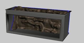
I was speaking to CJ from Crossley Architects yesterday. He said that he had been experimenting with creating freeform rocks in Meshmixer and bringing them into Revit. Here is an example of what he has produced:

As part of his workflow, he first of all used the STL Exporter add-in to export the fishtank context from Revit. This ensures that sculpting work is done in a way that can be accurately scaled and proportioned.
After importing the STL context into Meshmixer:
I’m glad to see that the Meshmixer organic workflow is getting some real-world Revit use!
Here is my previous post on Meshmixer:
What Revit Wants: Freeform and organic modelling from MeshMixer to 3ds Max to Revit