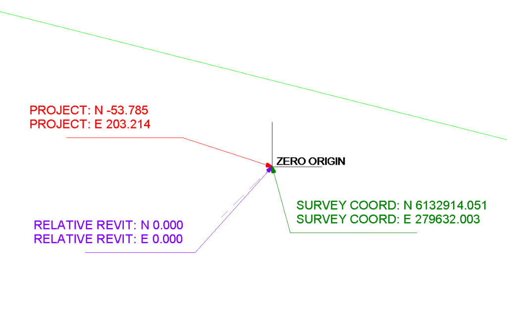
When exporting to IFC, you may find that Revit feeds the Survey Coordinates (or shared coordinates) to the resulting IFC file, when in fact you want it to be based on Project Coordinates.

If your project team is using origin-to-origin linking, it will be almost vital that you neutralize the Revit survey coordinates immediately prior to exporting to IFC.

This is quite easy:

  1. Make a new file based on a blank template
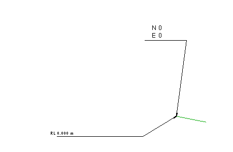
  2. Insert a origin locator dwg and draw a couple of model lines over the top (this is purely to give you something to “pick”)
  3. Save and close this blank RVT file (and keep it for future use)
  4. Link it into your live Revit project
  5. Use Acquire Coordinates and select the new, fresh, blank RVT file
  6. Save As this temporary RVT with neutralized survey coordinates to somewhere
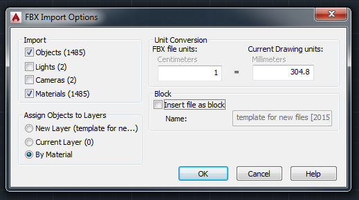
  7. Now Export your IFC

Your resulting IFC file won’t be confused about which coordinate system to use – it should now Append to Navisworks and other software using the same origin-to-origin coordinate system as that in the originating Revit project.

I have previously discussed going from Navisworks to Revit using FBX – 3dsMax – SAT. However, maybe we can do this without 3dsMax. Did you know that vanilla AutoCAD has a FBXIMPORT command?

1) Export FBX from Navisworks – it will ignore Section clipping planes, but it will respect the Hide/Required setting of the view. You can limit polygons (advised for big models)

2) FBXIMPORT in AutoCAD – untick Cameras and Block options as they can be problematic.
Then save DWG. (Note – see below for correct 1:304.8 import scale)
EDIT: If using Navisworks 2015 FBX export to version 2014, with Advanced Options units set to millimeters, you can import to AutoCAD 2015 with 1:1 scale factor (using latest service packs)

3) Open Revit and Link in the DWG.
For this example, I used Origin to Origin as I wanted to try round-tripping back to Navisworks.

Once I exported the NWC and put it back into Revit, I noticed the file was out of scale. Now, I experimented with a few different scale settings, but everytime it was a scale of about 30 or 300 wrong. 1 foot = exactly 304.8 mm. Evidently, the “internal” units of an FBX are feet. So, when we import to AutoCAD we need to use this setting to translate to mm:

This time, when I exported the Revit view to a NWC, and then appended it back to Navisworks – it can came back in exactly the right place. This workflow relies on using the internal Revit Zero point and Origin to Origin linking.

There you go – now you can roundtrip any mesh geometry from Navisworks to AutoCAD to Revit and back to Navisworks 🙂

Often, it is.  But if Project Base Point has ever moved in the life of the Revit project, then it probably won’t be.  Revit Zero (sometimes called the Internal Origin) affects things like FBX and NWC export (IFC too) when using Project Coordinates.

One way to find it is to make a DWG file with a couple of lines at 0,0,0 and link in Auto – Origin to Origin.  Another way is to make a Spot Coordinate that reports based on the “Relative” option.

You can theoretically  have 3 different coordinate records for a single geometric point, as this image shows:

You can read a bit about this at Revit Landscape.

Posted by Mark Petrucci:

  •  Did you know there is another point called the Startup Location? Be default, the PBP and SP are located on top of the Startup Location. What is the Startup Location used for? It’s used for linking models ORIGIN-TO-ORIGIN.
  • If you are an engineer and want to link the Architect’s project file origin-to-origin, you need to do this before you start the engineering model.
  • if a structural engineer lays out column grids without the architects model and then links files later, origin-to-origin will not work.
  • never, I repeat never move the building. I’ve read blogs on how to move a building using infinite view ranges. This does not work…

via
Applied Software Blog: Revit Shared Origin Survey Startup Base Location…