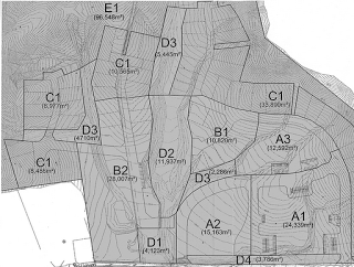
You receive a DWG file from a surveyor, and you need to get it into Revit.  You go through all the usual cleanup steps.  You have purged, scaled, done a write-block, audited.  You link the DWG into Revit, create the topo – and it looks like rubbish.

If your survey data has some severe gradient, perhaps relating to a steep retaining wall on the site, you may find that Revit does not model it ‘smoothly’.  Here is an example

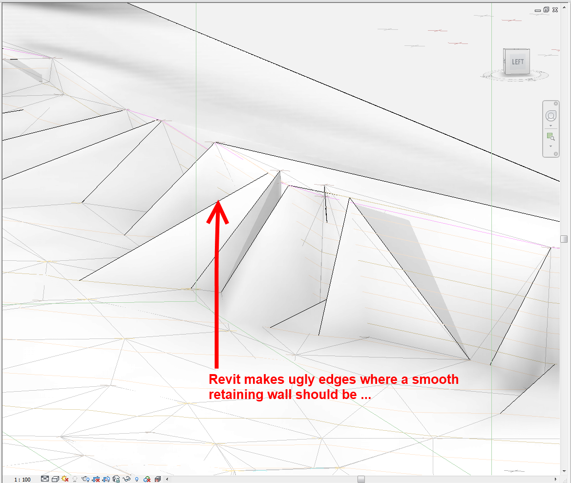
The problem is likely related to Revit’s triangulation method for topo surfaces.  You get weird flat surfaces where things should look much smoother and more organic.

Here is a quick workflow that I have used to add some realism to a survey DWG without sacrificing accuracy (note – this method uses AutoCAD Civil3D, you can download a trial):

  1. Open the survey DWG in Civil3D
  2. Create a new Surface (Right click Surface in the Toolspace – Create Surface…)
  3. Add the objects to surface (can be easier to isolate the necessary layers first).  To do this, expand the Surface node, then the Definition node, then select the Drawing Objects entry.  Right-click and choose Add…  You may want to add Contours separately using the Contours node.
  4. Edit Surface Style
  5. Contours – Contour Interval.  Change contour interval to something very small – I find 10mm works well
  6. Turn on the Contour layers for the Surface in: Surface Style, Display.  Also, set a new Layer to be the ‘layer’ for the Surface Contours (major and minor)
  7. Extract the newly created contour objects (select the TIN Surface and click ‘Extract Objects’).  To make my site look better in Revit, I actually had to export the Triangles as well.
  8. Select the extracted Contours / Triangles and save them out to a new DWG file (you can use write-block or the inbuilt Export command in C3D). You will need to take some geometry from the source file (like boundaries) so that you can locate these new contours in your Revit model.  Or keep them in the same file with the new layers you made in step 6.
  9. Import this new ‘high resolution’ contour plan into Revit
  10. Use these contours to make your topography (select only the appropriate layers when using Import Instance while creating Revit toposurface).
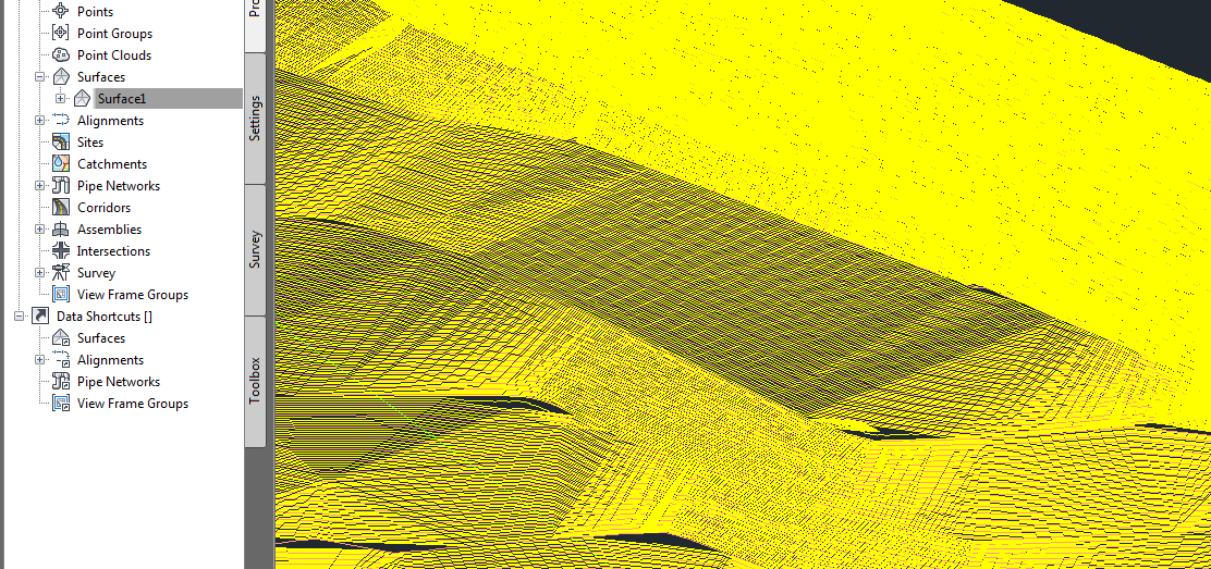
Lots of contours here – thanks Civil3D

The result?  Something with a much more ‘organic’ appearance:

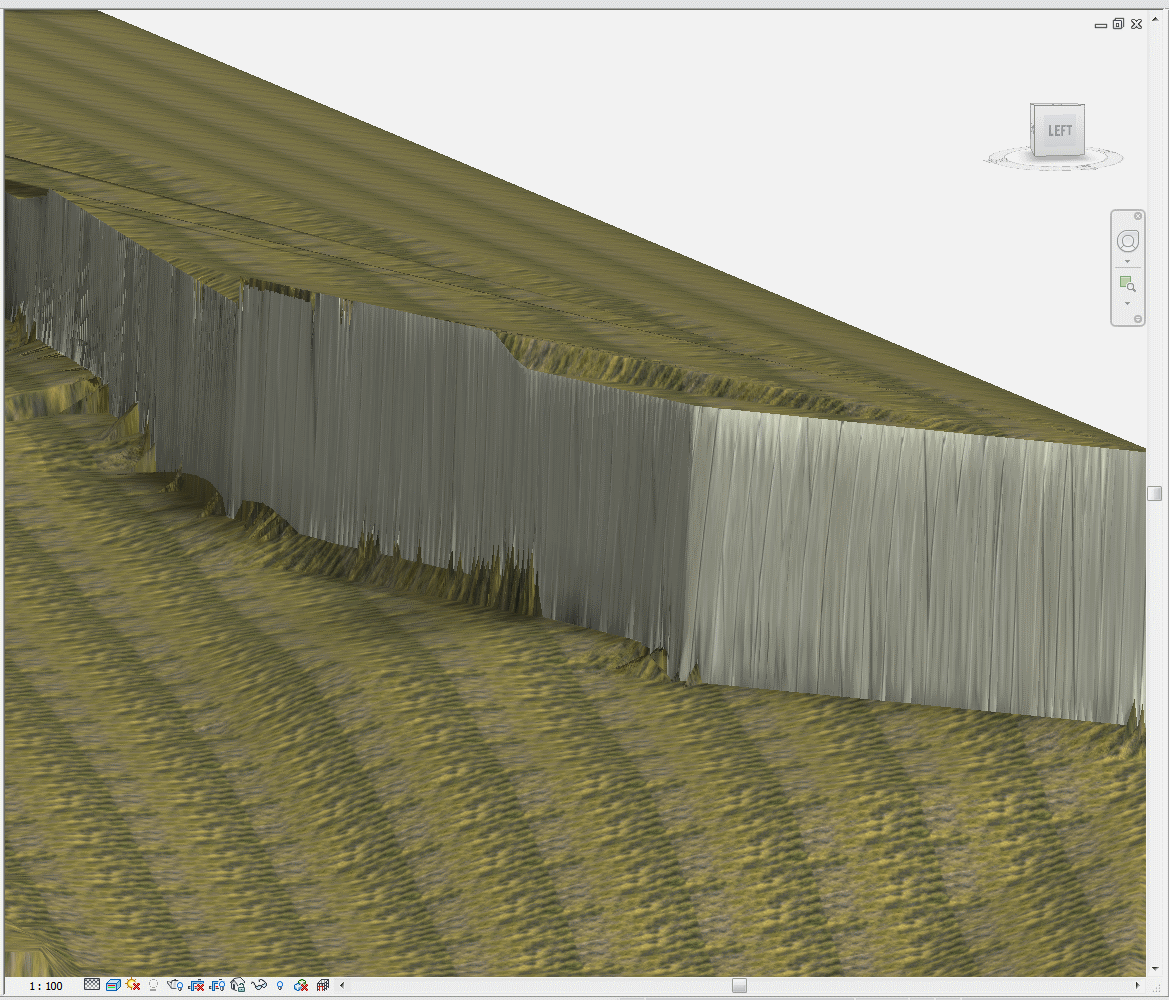
Better Revit surface (Realistic View, Edges off, Subregion applied)

Obviously, this method has a couple of caveats:

  • it will take a bit of processing power, both on the Civil3D side and on the Revit side
  • once you have your high resolution data in Revit, it will mean you are dealing with lots (thousands) of points in the topo – you have to decide if the nicer looking surface is ‘worth it’ to you 

Also, using my Quadro FX580, if there were too many points, my computer would basically just hard-crash to a BSOD – save often!  I ended up switching to software emulation (turning off Hardware Acceleration in Revit).

      You have a scanned image of a Contour Plan, and you want to convert that raster image into useful vector data.  How do you go about it?

      In the past, I would have used vanilla AutoCAD to trace the contours to polylines, then I might ‘spline’ them, then convert back to polylines (using a LISP tool), set all the elevations properly, and then import to Revit, then Create from Import to make the Topography.  Fun!

      However, this week I have fallen in love with a new tool.  Its called AutoCAD Raster Design.  I’ll admit – it’s not perfect.  But it is smart, and it makes the process much more bearable.  Just follow these steps:

      1. Download the AutoCAD Raster Design trial from here
      2. You need vanilla AutoCAD installed already…
      3. Install AutoCAD Raster Design
      4. Scan your image using scanning software.  Save as pretty much any format, such as a JPG.
      5. Open Raster Design.
      6. Click ‘Insert Image…’
      7. Just do Quick Insert to get your image in quickly.
      8. Now use the Histogram tool from the Raster – Image Processing menu.  Try and get a lot of ‘contrast’ into your image.
      9. Use the ‘Change Color Depth’ tool from the Raster – Image Processing menu.  Reduce to Grayscale and then Bitonal.  You really need to get the image into a ‘Bitonal’ form to make use of the vectorization tools.
      10. Use the Despeckle tool from the Raster – Cleanup menu to get rid of little dots…
      11. Now that you have a nice clean Bitonal Image, go to the Raster – Vectorization tools menu and choose ‘Contour Follower’.  This tool is pretty self explanatory – just follow the command prompts and experiment with the options on the command line.
      12. You may need to tweak the ‘Options’ under the Raster menu – Options.  On the Raster Entity Detection tab, tweak these settings to suit your image.  Also under the VTools Follower tab, tweak these settings to suit your Elevation Interval…
      13. Finally, you will want to turn on Raster Snap under the Raster menu.  This will snap to the Bitonal image elements quite nicely.

      Once you have traced all your contours and set proper elevations, save the DWG.  You will be prompted to also save the image…

      Now import your DWG into Revit and use it to make your Topography.

      Obviously, what Revit wants is for you to use accurate data at all times – so if you can get access to a proper DWG of the Contour Plan, do that!  In the meantime, you can use the abovementioned process to get the project under way…

      raster-2975375