From viewing the video, it looks like you just:

  1. Take some pictures with your drone and GoPro
  2. Upload to Recap 360 and make sure you get an RCS output
  3. Link it into Revit and do your conceptual modelling
  4. Visualize the model using the site context from the linked RCS point cloud

Easy!

Here’s the video:

Heads-up https://twitter.com/Alex_BIM_AJP/status/479897809634988033

Over the years, there have been a few attempts at modelling a Mobius Strip (or band) in Revit.  The BIM Troublemaker had a go back in 2010, Chad also tried in the comments, and The Proving Ground showed a method with RevitPythonShell.  Another guy tried using a massive rig on Youtube (skip to 7.55).

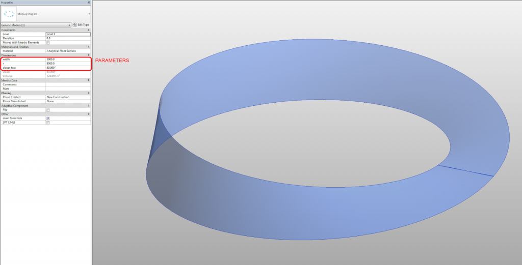
For me, the conceptual analysis of this problem goes back to a fundamental question – is a piece of paper a surface, or a solid?  It is really both, depending on the accuracy of the equipment you are using to measure thickness.  When it comes to modelling it in Revit, I prefer to think of it as a surface – something with no inherent thickness, just a piece of stuff that we twist 180 degrees and try to stick back to itself.

Similarly, I’m more concerned with making the Mobius Strip out of one piece (one “Create Form”), rather than two pieces.  And I’m not too worried about seeing a single seam line – even the piece of paper Mobius Band has visible sticky tape 🙂

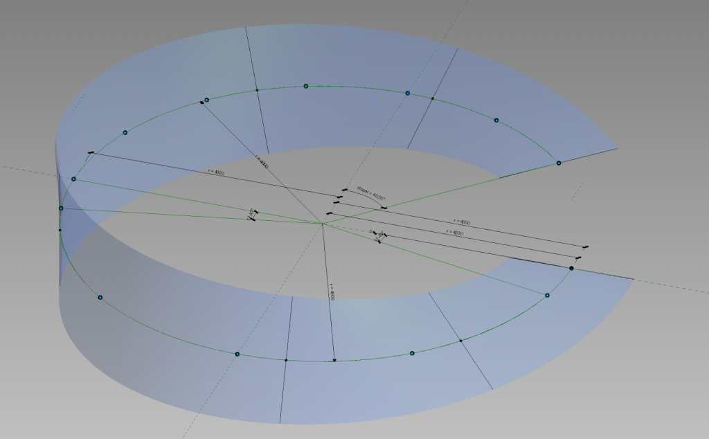
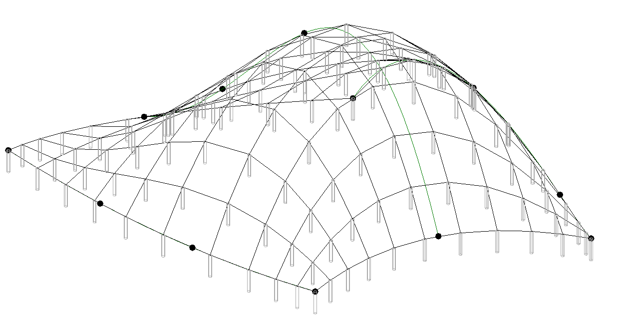
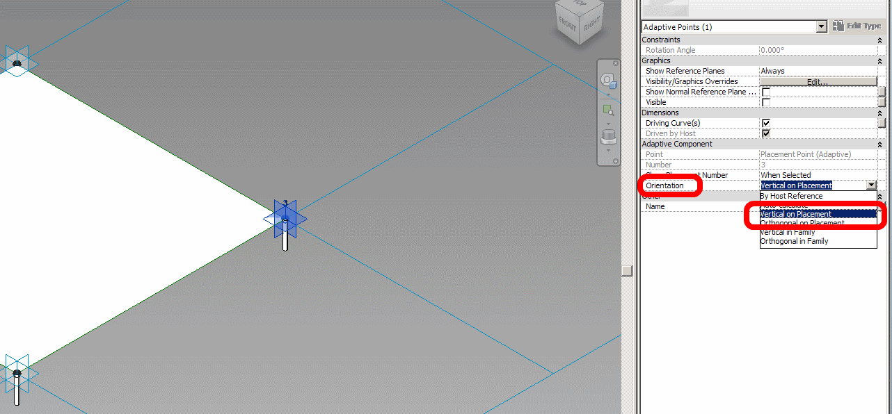
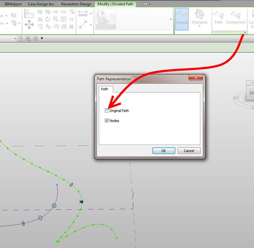
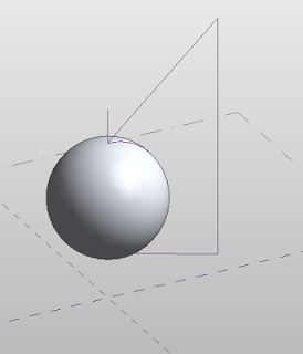
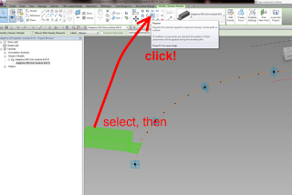
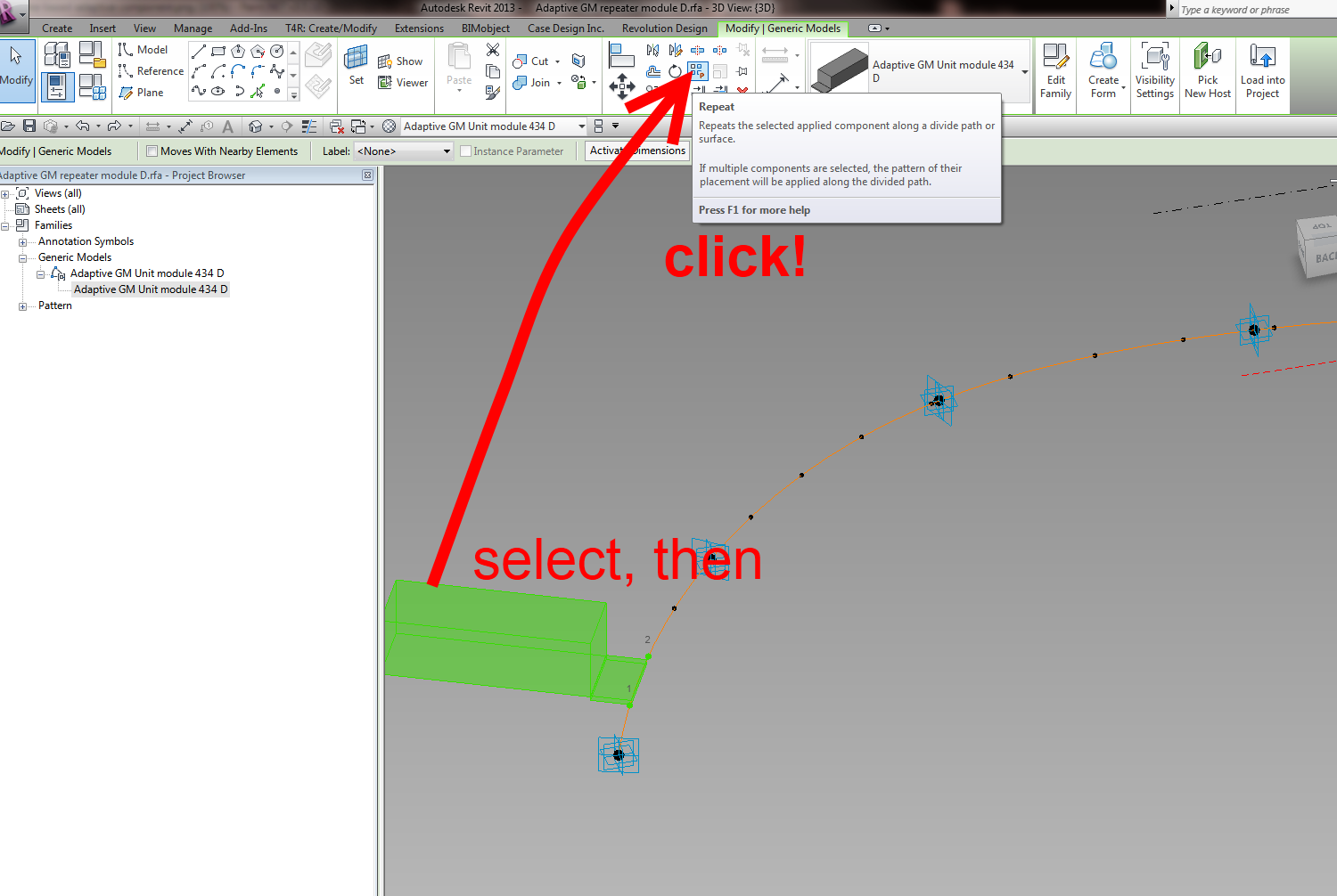
So in my example, I created a form derived from nested line families (parametric band width) that are hosted on Reference Points.  These Reference Points are driven by the Normalized Curve Parameter and Rotation Angle to set up a slowly twisting rig for the Create Form.  The Reference Points live on a Spline, that was placed on a Divided Path based on Arc / Circle segments.  This gives me two things – a simulated rig-driven “circle” that is actually a Spline (that has a parametric radius), and the ability to add a “Closer” parameter to push the two ends of the band together.

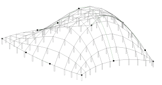
Hey, I know its not perfect, but it was a bit of fun!  Oh, and did I mention that the Wall by Face tool in Revit will happily generate a wall from this family in a single click?

You can download the example here:
https://drive.google.com/file/d/0B1dGdRkpk2beZ0FaMDIxai15aUE/edit?usp=sharing

It is an interesting add-in for Revit that can import point data into the conceptual environment.  It was written to “narrow the gap between computational concept design, terrestrial laser scanning and Building Information Modeling.”

Video:

Download page
Version 2.1 has just been released (25 May 2013)

Introductory page

Some info:
GreenSpider conveniently parses ASCII text files representing 3D vertexes, whether generated by computational modeling software or terrestrial laser scanning equipment.

Once installed through this installer package on Windows-based pc’s, GreenSpider 2.1 can be accessed in Revit mass modeling environment.

GSpoints and GScurves. The first one simply imports vertex point cloud as reference points in mass modeling environment, while the second traces a spline interpolation among imported points sorted through a TSP process, in order to build surfaces after recursive .GSP imports.


Decimated laser scanner point clouds are imported this way in Revit as many times as needed (using a reset function every time in Translator module), and generated curves can be used to originate surfaces very close to their real geometry.

via
GreenSpider – The Autodesk Revit point clouds plugin – TC Project

Heads-up:

Try this:
Make sure that you are using the Face option for placing the component.
Turn off the Original Path by selecting the Divided Path and using:

Start the place Component command.
Make sure that you pick a Node on the Divided Path to place the Component.

The Repeat button should now be visible.

Note: you can set a Node of the Divided Path as a workplane (the Placement Plane dropdown in the Options bar will read “Divided Path”), but placing a Component on such a workplane will likely mean that the Repeat button will be grayed out.

  1. Make a rectangular extrusion form
  2. Make a revolve form using funny looking profile shown above – switch to void
  3. Cut geometry, and then adjust grips as necessary to make it look nice

Download the file 

(dissolve it if you want to see how it works)

In response to:

You will find below a visual diary of some site master planning options – the Divide and Repeat tool was used to layout out the units.

Here is a very concise how-to:

  1. Make a new Mass or Adaptive family (in-place or component)
  2. Draw a Spline
  3. Select it and hit Divide Path
  4. Place a two-point based Generic Model Adaptive family spanning two of the points
  5. Select it, and then click the Repeat button

The images below will tell you more:

Further reading:
Use Divide and Repeat to Create A Curved (elevation) Railing – WikiHelp

Julien Benoit has put together a nicely paced introduction to Adaptive Components.

Some quotable quotes:
“The future of Revit family creation – adaptive components.” (at time 1:13:52)


“all our knowledge of families will die :)”
By attendee gaby424

Check it out at:
Adaptive Components By Julien

also on Wikihelp at http://wikihelp.autodesk.com/Revit/enu/Community/Examples/Basic_Adaptive_Component_Families