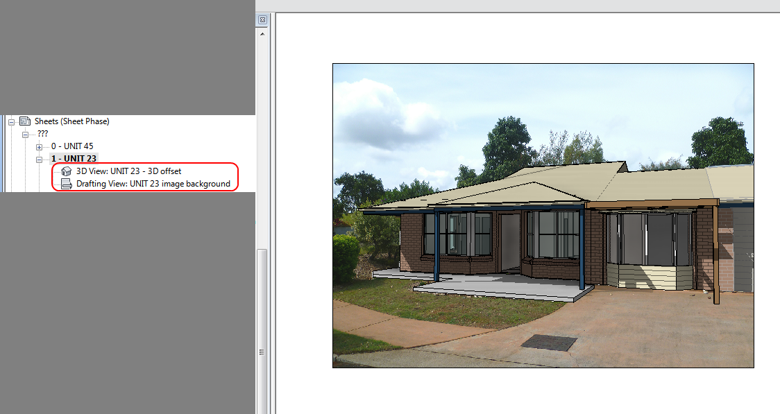
I have spent hours trying to figure out how to take actual camera locations from 123D (Photofly) and get them into Revit as ‘real’ cameras (3D views). I thought it would be cool to be able to use a real-life camera location in Revit, because then you would already have the existing scenery as a background image (because 123D Catch would have used it in processing the model). This was partly in response to this comment.
Its easy to export an FBX from 123D Catch, and open that in 3ds Max – you get cameras, yay. You can use FBXIMPORT in AutoCAD and you get the named views (cameras), yay.
However, I have not been able to find an equivalent process for Revit. At this point, I have to admit defeat.
My big idea was to convert the FBX into IFC with view information in the schema, and then open that IFC in Revit. Sadly, I kept coming up against problems. AutoCAD Architecture can import FBX and then export IFC, but the 3D views do not seem to come through.
One possible workaround would to compose your presentation in Showcase – you can export from Revit to Showcase, and you can also export an FBX from 123D and bring that into Showcase too. But I want a purely Revit way.
If you have any thoughts on how to make this happen, PLEASE comment 🙂
Here is a list of links and notes that you may find useful. There are some really cool resources on IFC available now – read on below:
NOTES on FBX and IFC
Autodesk sign in is required on 123D Catch to actually activate the Export feature to allow exporting of FBX.
Explanation of the export formats available from 123D (formerly Photofly):
| Menu Command |
Format |
Contents |
 |
.3dp |
The 3D photo scene contains cameras, reference points, 3D mesh, reference lines, and distance measures. This is the native format for Project Photofly. |
 |
.dwg |
The drawing contains reference points and reference lines. |
| .fbx |
The Autodesk FBX asset exchange file contains the 3D cameras, the photo textured 3D mesh, reference points, reference lines, and reference labels. |
| .rzi |
The ImageModeler file is a subset of the 3dp file based on what was selected at the time the photo scene was exported. |
| .obj |
The OBJect file contains the photo textured 3D mesh. |
| .ipm |
The Inventor Publisher Mobile file contains the photo textured 3D mesh and can be viewed with the free Inventor Publisher Viewer available in the Apple iTunes App Store. |
| .las |
The binary LASer file contains the 3D point cloud that was automatically extracted from the pixels of the source photographs. The LAS file format version is 1.2. |
via
http://labs.blogs.com/its_alive_in_the_lab/2011/09/viewing-ipm-files-generated-by-project-photofly.html
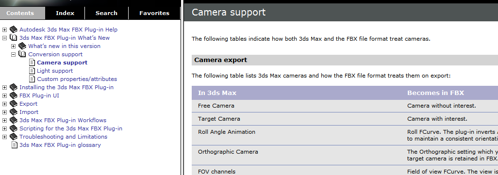
Camera Support – 3ds max and FBX
http://download.autodesk.com/us/fbx/20112/3dsmax/files/WS1a9193826455f5ff6026605b1181237e94650be.htm
AutoCAD Architecture IFC export information
http://exchange.autodesk.com/autocadarchitecture/enu/online-help/browse#WS73099cc142f4875510b13df10ec0b2c48a-7a62.htm
3D views can be export FROM Revit TO AutoCAD Architecture
http://wikihelp.autodesk.com/Revit/enu/2013/Help/00001-Revit_He0/1468-Document1468/2171-Print_Ex2171/2172-Export2172/2245-Structur2245/2251-Exportin2251
List of IFC softwares, tools and viewers
http://www.buildingsmart-tech.org/implementation/get-started/ifc-toolboxes/ifc-toolboxes-summary
IFC schema information for views (plans, sections, 3d views etc)
Context
http://www.buildingsmart-tech.org/ifc/IFC2x4/rc2/html/schema/ifcrepresentationresource/lexical/ifcgeometricrepresentationcontext.htm
Subcontext
http://www.buildingsmart-tech.org/ifc/IFC2x4/rc2/html/schema/ifcrepresentationresource/lexical/ifcgeometricrepresentationsubcontext.htm
DDSViewer – can view DWG and IFC
- also a very easy way to open DWG and save as PDF!
http://www.dds-cad.net/132x2x0.xhtml
To get a free version of the DDS Viewer, visit the ftp server and download DDSViewer.exe
IfcWebViewer – online web viewer for IFC using WebGL
http://code.google.com/p/ifcwebserver/wiki/IfcWebViewer
Exporting cameras as .3ds files using Flame
http://wikihelp.autodesk.com/Flame_Premium/enu/2013/Help/01_Flame_Premium_–_Flame/2037-3D_Compo2037/2267-Action%3A_2267/2274-Importin2274/2276-3ds_Max_2276
Vectorworks and 3ds
http://www.scribd.com/doc/34074946/128/Importing-and-Exporting-in-3ds-Format
Showcase can import views from FBX files
http://download.autodesk.com/global/docs/showcase2013/en_us/index.html?url=files/Help_ImportSettings.htm,topicNumber=d30e2896
IFC to OBJ:
IfcOpenShell