To make the swappable profile, use a Generic Model Adaptive template, but don’t add any Adaptive points.  Set the 2 reference planes in the template to “Defines Origin”.  You can parametrize this as much as you like (just don’t use Reference Lines – you need a closed profile of Model Lines as per any Profile).  Then, load this into another new Generic Model Adaptive family.  Host the Profile component on a hosted point (that is, one that has been placed on a line).  You will need one of these nested Profiles at each end of a line to control the form properly.

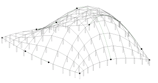
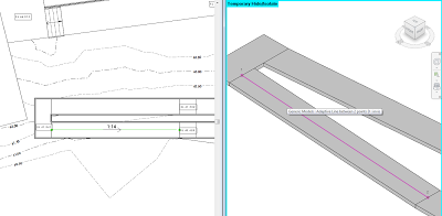
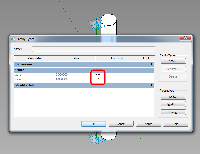
I am in the habit of using hosted points to host Profiles now.  For example, in a 2pt Adaptive with a Reference Line, I will add 2 hosted points to the Reference Line to carry the Profile instances.  These hosted points will be forced to the end points by using a parameter for zero, and another one for one, and forcing these values by putting 0 and 1 in the Formula box of the Family Types dialog (see image).

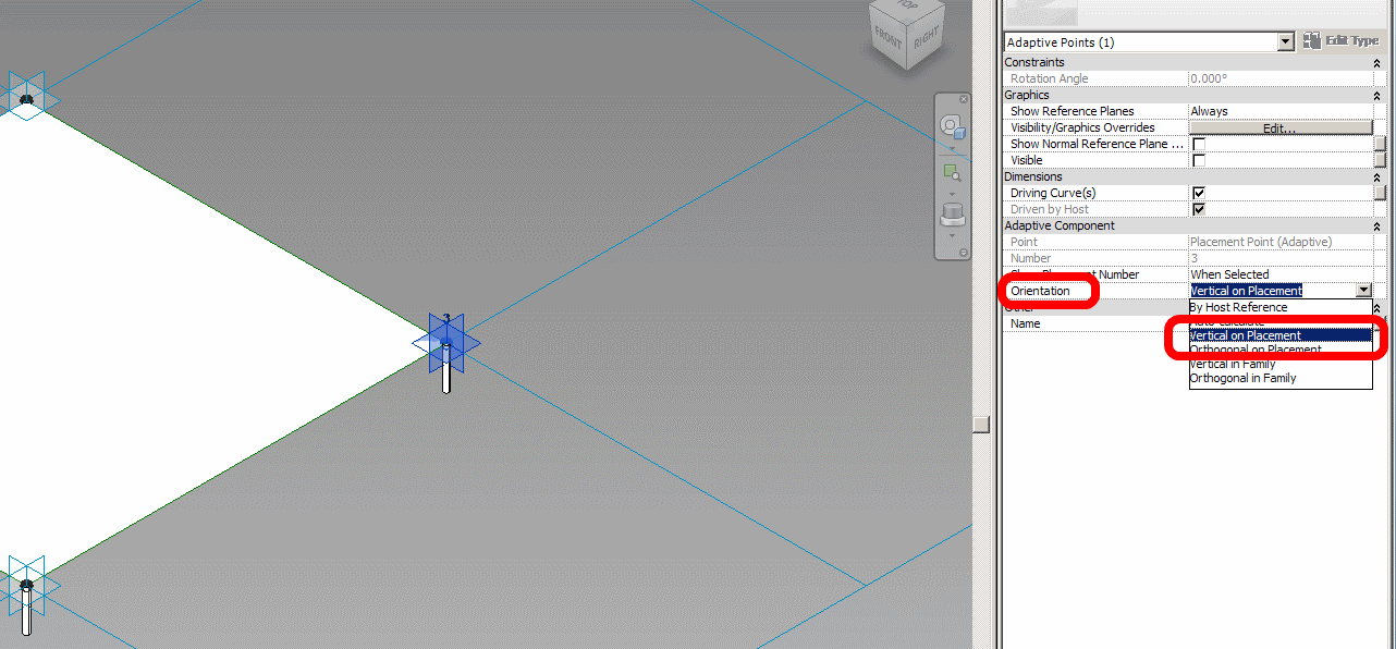
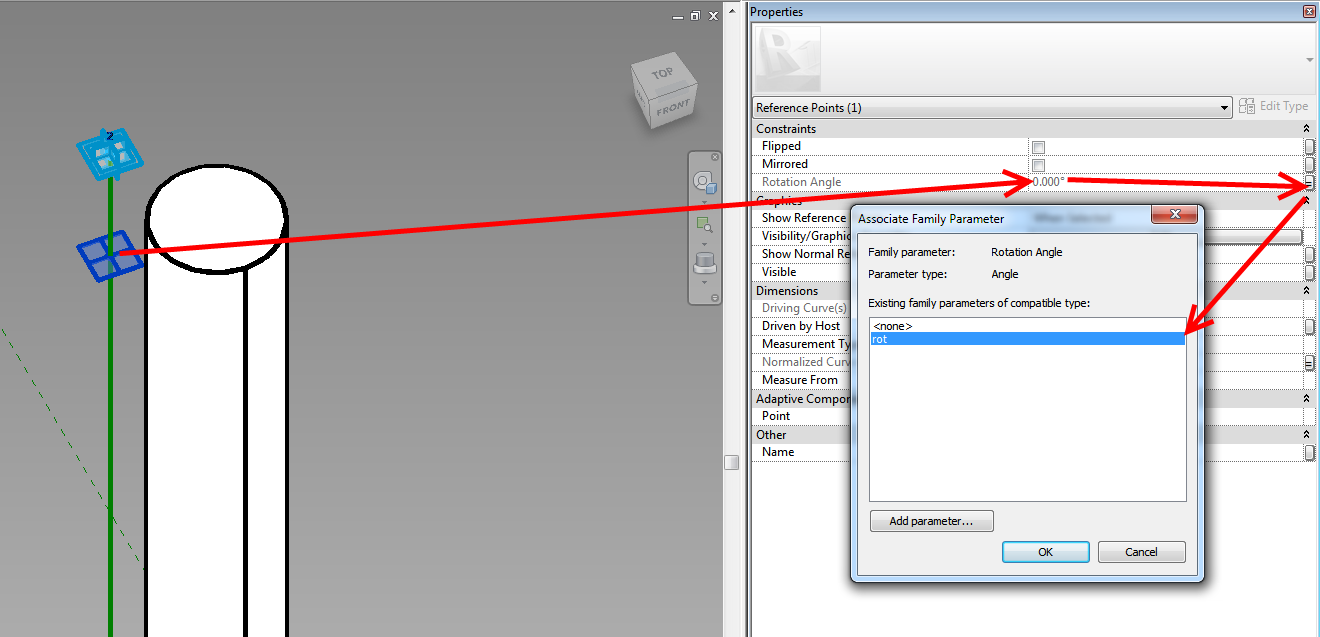
If you are using hosted points (make a new point, and drop it on a Reference Line – it will be come a small dot if it is hosted on the line), you can actually adjust the rotation Angle using a parameter – this makes it easy to rotate the profile around the hosting line.

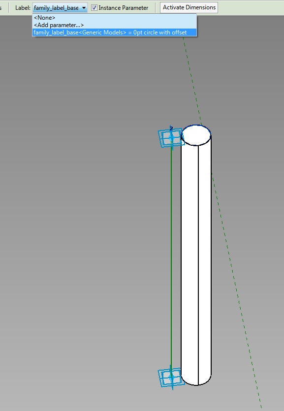
Here is the really cool part – you can apply a Label parameter to the Profile instance in the host family, and then directly swap Profile shapes (different nested RFAs or types in the same RFA, both work).  This even works from the Project Environment.

If you want to drive the profiles parametrically via the host family, you will have to make them un-Shared (otherwise you can’t map parameters from Type to Host).  You can swap between un-Shared and Shared profiles using the Label parameter.

Finally, to create the form, select the Profile families (the ones at each end of the Reference Line) and click Create Form.  Unlike other form creation scenarios, you do not want to select the “lines” by Tabbing through – you actually want to select the family itself.  The Label parameter will allow you to swap these families, which will drive the Form.

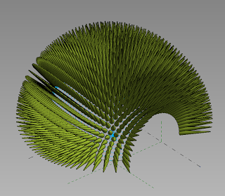
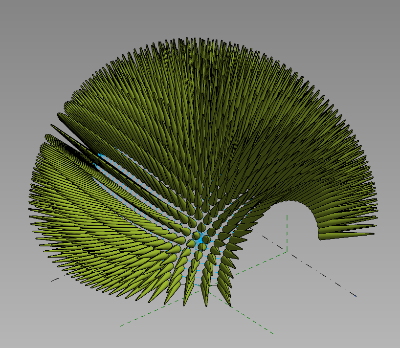
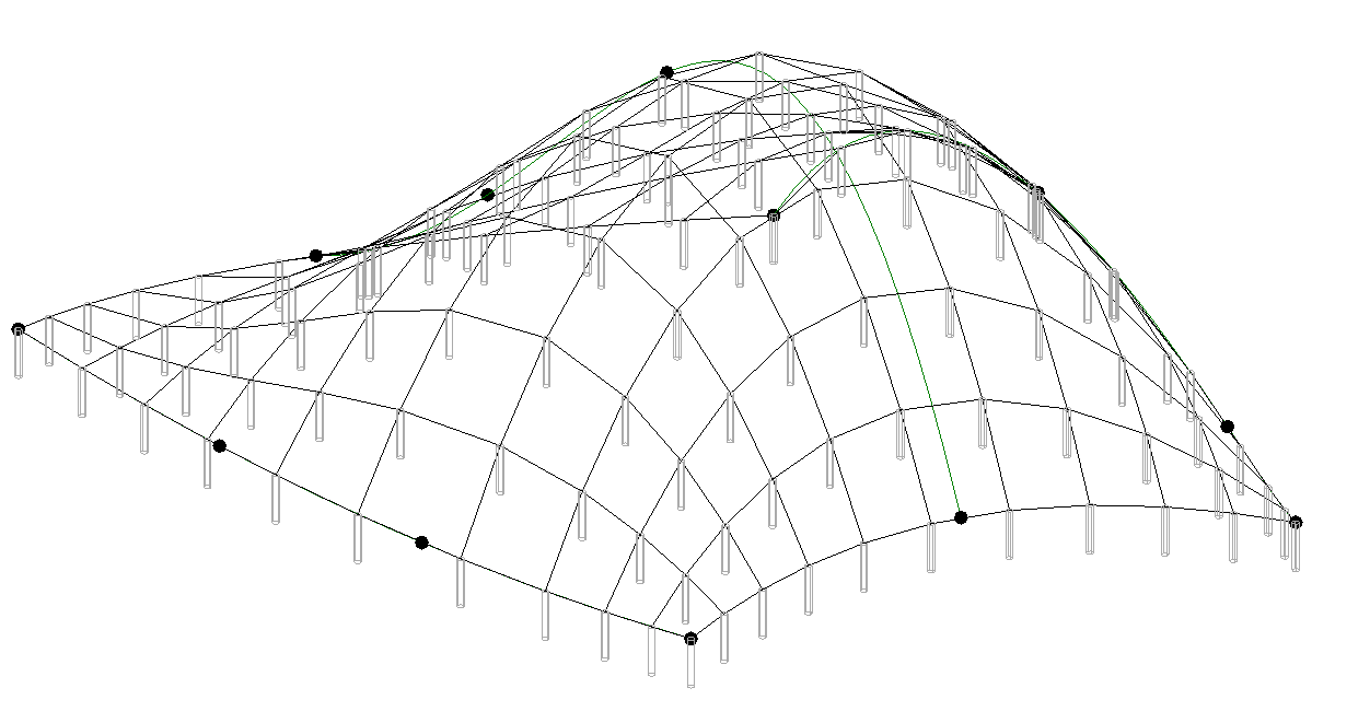
In the image below, all of these are one Adaptive family – with profiles swapped, and parameters adjusted, including rotation about the axis.


Download the above example here

Credit:  I’m fairly sure I read about this general idea somewhere… it was a while ago.

After reviewing Andy’s and Tim’s recent posts surrounding trees and reaction, I would like to contribute this little idea.

Its a very simple setup – just a 2pt Adaptive with an “extension” (created by controlling the host reference planes of a couple of points), that has been loaded in and repeated across a treetop form.  As you move the centre adaptive point up and down, the surrounding spines react to maintain a perpendicular relationship to the main form.

I have added parameters for the extension length, and top and base radius of the spines.  You can adjust these in the Project Browser by modifying the Type Properties of the 2pt family.

Here’s the family for download.

You can host profiles onto the nodes of a divided path (line), however they can’t be conventional Revit profiles, they must be adaptive components – they can be quite simple drawn in 2d (XY axis) without even placing an adaptive point. When hosted on the nodes they will be automatically oriented perpendicular to the divided path. You can then “Repeat” them along the path – the number is then easy to control. The challenge is how to create and manage variations in the Repeater – it can be done but is not so easy.
via Tim Waldock’s comment at
http://wikihelp.autodesk.com/Revit/enu/2014/Help/0000-New_in_R0

In Revit 2013, you can’t tag the slope of ramps in Plan views using the Spot Slope tool.  There are workarounds out there already, but here is an easy one:

  1. Make a new Generic Model Adaptive family with 2 Placement Points
  2. Make a spline between these two points (select them and then hit the spline by points button).  Set its category to Invisible
  3. Load this Family into a Project, and using a 3D view, place it at the centre line of a ramp (the two points should snap to the correct location in 3D)
  4. In a Plan view, use the standard Spot Slope tool in Revit – just pick the adaptive component “line” that you just placed.

EDIT 
As I mentioned above, there are other workarounds for this. One is to put a slope arrow on an adjacent Floor, then copy it on top of a Ramp. It works!

Check out comments and video link below…

Link:
http://www.youtube.com/watch?feature=player_detailpage&v=IJD14dDUKbU#t=71s

I actually found this did not work too well in Revit 2013 (no problem in 2012).  However, after a bit of fiddling, I have created 3 files (one for Revit 2012, 2013 and 2014) – all of which have spot slopes on Ramps that can be copied around.  Here is the link:
View / download


Remember Julien Benoit’s adaptive component tutorial from a year ago (link here)?  Well, Julien has made something pretty cool and posted it on RFO.  It is basically a 4 point adaptive component that calculates the area of the resulting surface using Bretschneider’s formula.

Julien’s solution (using an intense formula):
File Type: rfa AreaTool#2013_AC_CP_4P.rfa 208.0 KB

This is the formula, if you are interested (!)
sqrt((P – A) * (P – B) * (P – C) * (P – D) – ((A * B * C * D) * cos((BB + CC) / 2) ^ 2))

Alfredo’s more volumetric solution:
File Type: rvt Project_panel_areas.rvt 960.0 KB

Note: you will have to login to RFO to download from these links.

Read the whole thread:
AC curtain panel as measurement tool