And I think you know why…

What Revit Wants

And I think you know why…
So I see that the factory has posted about the Revit Options Bar duplicates or moves objects when selected error.
Greg Arkin also re-posted this on his blog.
What I find quite funny is that I already posted this fix in August 2009.
I may be crazy, but don’t you think it is a bit weird that a humble blogger and Revit user from Australia has posted a fix about 8 months in advance of Autodesk themselves?
Does “The Factory” have someone out there reading our blog posts? If they don’t, I think it might be a good idea 🙂 Particularly with 2011 just around the corner…
This is the first post in a new series for this blog, called RATAS Solutions. What is RATAS, and why should you make sure you read every one of these posts? Well, RATAS is what you say when ‘Revit Appears To Act Strangely’. Try it out, while you are sitting there…”RATAS” (pronounced rat-ass…feels good, doesn’t it? Now, whenever you are getting annoyed, and Revit seems to be acting strangely, what do you say? “RATAS”, that’s what!
RATAS Problem #1
File-A.rvt is linked into File-B.rvt. In File-A, you have created a new Phase Filter called ‘Custom Phase Filter 1’. You have mapped phases from File-A to File-B (using the Type properties of the link File-B). When you apply ‘Custom Phase Filter 1’ to a view in File-A, the File-B link does not obey the filter (for example, demolished items are still shown, even though they should not exist in this phase). You check and you have definitely set the File-B Visibility/Graphics to ‘By Host View’. So, you change the Phase Filter to ‘Show Complete’ and everything works! What is happening? RATAS!
RATAS Solution #1
Revit understands the Custom Phase Filter 1 for the Host View (in File-A). However, when Revit attempts to apply this Phase Filter to the File-B link, something breaks. File-B doesn’t have a definition for Custom Phase Filter 1 present. When you change to ‘Show Complete’, it works, because File-B DOES have a definition for this Phase Filter present.
The Solution? Open File-B, and create a new Phase Filter with the same name (Custom Phase Filter 1) and properties as the Phase Filter in File-A. Save and Reload…and the problem is fixed!
Now, I put a lot of thought into naming RATAS – because while Revit often ‘appears’ to act strangely, usually it has good reason to act the way it does. Thus, we get back to the same advice I have given before – you need to try to understand What Revit Wants, so that you can solve these kinds of problems yourself.
The existence of the Adaptive Component feature isn’t really a secret. But it is one of the coolest things about Revit 2011. Imagine a family that lets you push and pull points in 3D space…and imagine that those points then drive all the geometry inside the family.
It is very nearly cool. However, I say ‘nearly’ because there are definitely some serious limitations. Autodesk has come out and listed some of these limitations, such as:
adaptive components can only be placed in a conceptual mass family, an in-place mass, a curtain panel by pattern family, or another adaptive component family.
This is a real shame, because this is going to be one of the most powerful modelling tools in Revit 2011. If only we could use them in all categories!
Look out for some very cool forms in the next few weeks, as users start to get the hang of Adaptive Components. And look out for some very neat workarounds and tricks to get the most from this new feature.
No, not aeroplanes: we are talking about Reference Planes. So, the tip is:
Always name reference planes that you intend to keep and use.
Reference Planes lie at the very core of What Revit Wants. Revit is a program, so it needs parameters. In order for understand objects in 3D space, it needs to establish a ‘plane’ to work from. Obviously, Reference Planes are the basic, garden variety type of Revit plane – there are also Grids and Levels. These are just planes that do some special things, like host a view.
If you want to quickly see what planes exist in your project, open a 3D view and then start the ‘Set Work Plane’ command. This dialog shows all the NAMED planes, including grids and levels. Can you start to see why you should name Reference Planes you intend to keep and use? That way, you can quickly make them ‘current’ by using this command.
This also allows you to clean up your drawing. If you adopt this tip, let’s say you come back to a drawing a few months later and it is absolutely cluttered with Reference Planes. Which ones can you safely delete? Well, you have named all the important ones, so you can delete the rest!
Over the past few years using Revit, a few tips just keep coming up. These are things that Revit consistently wants you to do, in order to have a pain free modeling experience. I call these ‘SuperTips’ and I will progressively reveal these on this blog.
SuperTip #1 – Don’t make too many levels
It may seem like a basic thing to say, but many amateurs will get in and create levels for everything little thing, which results in a huge mess as the project progresses. Try to make the minimum amount of levels possible. These should always coincide with the major structural floor levels of your building. An excess amount of levels will make the project difficult to work on and difficult to work in. Please refer to this previous post for some tips on how to deal with this issue.
If you create heaps of levels, it will be very difficult to track which level elements are created on. For assistance with this, please refer to this previous post.
Instead of creating unnecessary levels, consider using reference planes in areas where you would normally put a superfluous level.
His blog is named What Revit Wants which, reminds me of a Wham! video, but maybe I’m just dating myself.
From http://www.architecture-tech.com/2010/04/and-real-winner-is.html
And here is a summary of the tips that I sent to them:
tip on Impression workflow that many have read
Direct readers to http://www.revitprofessionals.com/, where I have created a list of Revit bloggers3D views – shaded vs rendered
also https://wrw.is/2009/10/how-to-use-new-keyboard-shortcuts.html
Thanks for the mention guys, and I look forward to checking out the book!
You would likely agree that the Text tool in Revit still leaves a lot to be desired, not least of which would be some decent bullets and numbering features. No doubt most of you are using Key Schedules to get around some of these limitations when creating note blocks (as described in this PDF from an AU class).
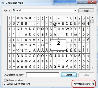
However, are you aware that you can put symbols into Revit schedules? The easiest way to described how this works is to use the Character Map. To access the Character Map, go to Start-All Programs-Accessories-System Tools and open Character Map. I have created a link to the Character Map in my Quick Launch toolbar.
So how does this thing work? Well, let’s say you are using the Arial font in Revit. Select Arial in the Character Map. Now, have a look through all these different symbols. When you find one that you like, click on it, click ‘Select’ and then click ‘Copy’. Now, go into a Revit schedule or text box that is formatted with the SAME FONT (ie. Arial) and Paste (using Ctrl+V is easiest). There you go, you have a nice symbol to play with!!
The quicker and easier way is to use the inbuilt hotkeys. For instance, to add a ‘squared’ (little superscript 2) symbol, just hold down Alt and press the keys 0 1 7 8 (just type the numbers one after the other while holding Alt). You can find out which keystroke to use by looking in the bottom right corner of the the Character Map (see below).
There are quite a few things you can do once you know how to use this. See below for a Key Schedule I made with a ‘column’ containing a rightways arrow symbol.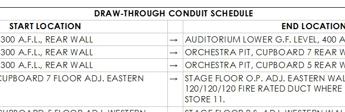
You may have seen the long list of fixes already available for Revit 2011. Perhaps the first release will be stable, perhaps it won’t, but many of you might like to consider running Revit 2011 in a virtual environment (at least to start with).
I wanted to play around with Revit MEP and Revit Structure, so I :
This is a stable and safe way to test Revit in a ‘sandbox’ type environment – where really bad things shouldn’t happen. There are some minor issues – it can be difficult to get 3D Hardware acceleration working in a virtual environment. But for testing purposes, its great.
The virtualisation software that I used was VirtualBox, as this allows for 64-bit guest operating systems.
If you don’t have a copy of Windows 7 64-bit handy, you can download the media from the internet. You can also reset the activation period to allow for 120 days use.
Please note that you will need some decent hardware to virtualise Revit in a 64-bit environment 🙂
EDIT In Revit 2012 and newer, the quickest way to identify paint is to use the Remove Paint tool. This does not load the Material selection panel, and will thus be faster. Also, switch 3D view to wireframe with Remove Paint to globally scan the project with your cursor for painted surfaces…
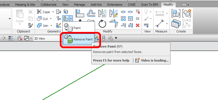
To find out what material is currently painted onto a surface, simply start the ‘Paint’ tool, then Tab select the surface (face region).
Revit will produce a tooltip showing the currently painted material, and this will also show up in the status bar at the bottom of the screen.
