Interior – rendering with Autodesk 360
The built-in Revit Mental Ray rendering engine – which is integrated among others in AutoCAD and 3ds Max – provides no explicit rendering and lighting skills excellent results in no time.
Yet often there is a requirement several perspectives – or more copies of a perspective view showing possible design options to render. This process requires when rendering locally active start the rendering process, after the elapsed before each process is complete.
With rendering in Autodesk 360 – a cloud-based service you use a total of 64 CORES SIMULTANEOUSLY. A rendering of the highest quality with the highest resolution then takes 10 to 13 minutes …… and: Your PC is in this time, with full performance at your service!
This allows, for example, different versions of a project to render a blow as you design maybe a fourth.
Read in this technical information on how to set the exposure values - which is particularly important in interior renderings – and the possibilities of rendering issue in Autodesk 360 have. In addition to the statue, and the panorama, you can also visualize since January 2013 and the SUN STUDIES ILLUMINANZEN.
Autodesk Building Design Suite 2013 Technical Information Page 1 of 15 March 2013
Autodesk 360 Account
To use the cloud rendering services, you must first create it in 360.autodesk.de 360.autodesk.com or an Autodesk ID if you do not already have one.
With the free account you 12 rendering operations are available for free
After login, you can activate your serial number under account details.
Depending on your subscription – product will thus increase the number of your remaining available credits.
Note regarding credits are available, and the acquisition of additional credits to these information.
Autodesk Building Design Suite 2013 Technical Information Page 2 of 15 March 2013
Interior Rendering: Setting Exposure
Enabling artificial light sources
Revit has initially a setting for each view render settings. This is accessed through the Properties palette, if you have selected an object.
Set here, you want to choose what exposure scene. In the example we choose to stand INTERIOR – SUN AND ARTIFICIAL.
For example, you choose EXTERIOR – ONLY SUN would not inserted lighting – Artificial light sources can be active or “turned on”.
This setting applies to both the local rendering, as well as for rendering in the cloud.
Warning: If you go into the settings of the GRAPHIC DISPLAY, see also the possibility to set this exposure. Note that you are NOT affect the settings for rendering, but only the way in Revit CAD graphics.
Autodesk Building Design Suite 2013 Technical Information Page 3 of 15 March 2013
The setting enabled interior lighting is not purely a graphical representation and due to increased computer utilization for constructing suitable.
Disable individual light sources
In the render settings you can turn off individual light sources. To do this in the list of ARTIFICIAL LIGHT.
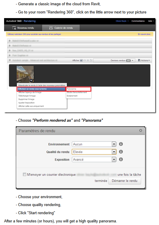
To create a rendering with these settings, click now in the 3D view CLOUD IN RENDERING.
With the button RENDER CATALOGUE take you directly to the area of your renderings and can download them there.
Autodesk Building Design Suite 2013 Technical Information Page 4 of 15 March 2013
Adjusting the illumination
Light distribution
The inserted Revit lights have in addition to the geometry of the lamp itself and the light source.
To adjust the light distribution, click the fixture and select EDIT FAMILY.
Select the beam and open the
LIGHT SOURCE DEFINITION:
Specify the shape of the light source and the light distribution.
Note: If you choose for the photometric light distribution network, you have family in the type of light the possibility of specifying a file * ies..
Autodesk Building Design Suite 2013 Technical Information Page 5 of 15 March 2013
IES data describe the light distribution of proprietary bulb. This information can for example be on the websites of ERCO free download:
ZUMTOBEL even offers the lights as Revit models with integrated illumination data.
Shown in this example we are using a point-like spot in the picture of the light source definition.
Brightness: wattage and efficiency
Select a fixture within the project and open the type properties.
The WATT INT (type parameters of the lights) regulated together with the efficiency of the brightness of the lighting. (In reality, of course, describes the units of Watts, the power).
A 20Watt LED is brighter than a 20 Watt light bulb – which means it has a higher efficiency.
Thus, Revit – in theory (if one of the light color aside) get from a 20-watt LED lighting family the same light as a 80 watt incandescent-family:
Autodesk Building Design Suite 2013 Technical Information Page 6 of 15 March 2013
Example: EV 9, Light color 4230K,
20W * 80W * 400lm/Watt = 8000Lumen 100lm/Watt = 8000Lumen
80W * 20W * 100lm/Watt 400lm/Watt
Light color
The light color is set in the type parameters. When the color of light, the light is all the more
“Warmer” the lower the value (2800 Kelvin light bulb, fluorescent lamp cool white 4230 Kelvin) is:
Example: EV 9, 80W * 100lm/Watt
Light color 4230K Light color 2500K
(Cool white) (old bulb)
Autodesk Building Design Suite 2013 Technical Information Page 7 of 15 March 2013
Brightness: Exposure Value
If a scene despite a subjectively appropriate wattage with matching efficiency too dark, this is usually in the setting EXPOSURE VALUE – comparable to the aperture of a camera. If you’re shooting in an artificially lit room with supposedly sufficient to large aperture, the picture is too dark.
Example: Light color 4230K, 45W, 150lm / W:
EV 7 9 11
(Large aperture = less light = darker image)
Autodesk Building Design Suite 2013 Technical Information Page 8 of 15 March 2013
These settings can be both when rendering locally as well as adjust 360 Autodesk rendering even after the rendering process:
On Autodesk 360 with the right mouse button on the rendering and select ADJUST EXPOSURE:
Light loss factor
As the name suggests, this type parameter describes the lamp as the light decreases rapidly with increasing distance.
Example: Exposure: 9, Light color 4230K, 45W, 150lm / W:
Light loss factor 1 2.7
As you can already see in the dialogue, causes a bigger factor less light loss:
Autodesk Building Design Suite 2013 Technical Information Page 9 of 15 March 2013
Exposure: native or Advanced
When sending a view to render service to the Autodesk 360 you have the option to choose between these two exposure settings.
What is the difference here?
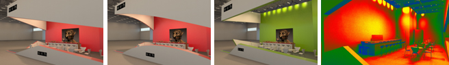
By default EXTENDED EXPOSURE SETTINGS that simulate the right lighting conditions, automatically applied to all renderings. To use instead of the defaulted exposure enhanced the native settings for exposure of Revit, you render the image again – the Render from catalog or from the software and select exposure NATIVE. Revit will then render with the settings that are used when rendering locally with Mental Ray.
You look at the two examples that the right image was optimized by the advanced exposure settings – the bright areas of direct illumination was reduced to the back wall. In addition, the red back wall has less reflective. Left: native exposure.
Autodesk Building Design Suite 2013 Technical Information Page 10 of 15 March 2013
Proper modeling of lights
If you want to create lighting objects or modify itself, pay attention to the correct position of the light source.
Sits as a light source in front of the luminaire geometry, the object radiates true of light, but the light appears dark in itself – which ultimately gives no realistic impression.
However, in the light or sitting behind a geometric object – eg with the material glass, white, high illuminance (Lens) – will also be illuminated by this object. The image looks more realistic.
Autodesk Building Design Suite 2013 Technical Information Page 11 of 15 March 2013
Output Formats in Autodesk 360
Within Autodesk 360, you can not only render still images. You have the following possibilities open (February 2013):
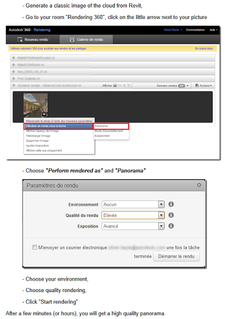
Panorama
A panorama you can render directly to standard definition of Revit out by sending in – Select dialog instead statue INTERACTIVE PANORAMA.
For better results you get when you first render a still image with high quality and resolution, and then click the Autodesk 360 surface the image with the right mouse button. Select PANORAMA AS RENDERING. The panorama is now rendered with the resolution of the still image.
To view the panorama you can do so online at the Autodesk open 360 account and navigate.
Alternatively, download the panorama as an image sequence down to your local computer. (See left).
To view a panorama offline, use
e.g. this tool.
http://bimblog.typepad.com/autodesk_bim_blog/2013/01/a utodesk-360-panorama pictures-off-ansehen.html
Autodesk Building Design Suite 2013 Technical Information Page 12 of 15 March 2013
Solar studies
New since January 2013 is the ability to render sun studies – and these come in the outdoor area more safe for use as indoors.
Choose Autodesk 360 a rendered still image and click on the image menu:
Select RENDERING AS SUN STUDY.
You can study the sun in the open 360 Autodesk account and play as a movie. Click in the context menu, right-click on START.
If you want to download the sun study, Autodesk will provide 360 the image sequence in the corresponding resolution.
The sequence can then be quickly and easily in programs like Camtasia or various freeware programs to convert a video.
Autodesk Building Design Suite 2013 Technical Information Page 13 of 15 March 2013
Illuminance
Also this option is new since January 2013.
Again, you choose an already rendered image and click on the shortcut menu, right-click AS RENDERING illuminance.
Of wattage, efficiency, light loss factor and light color, the system calculates the brightness at each point of the model.
The exposure values have of course no effect as the light parameters affect the brightness of the room, but not the aperture of the camera used – this determines only the image in the camera, not the reality.
Autodesk 360 created a still image with the graphical representation of the brightness.
All this means that in Autodesk 360 is a powerful analysis tool, which allows you to quickly and easily create professional lighting simulations
– Without in-depth knowledge of the lighting customer.
Autodesk Building Design Suite 2013 Technical Information Page 14 of 15 March 2013
Other features of the Autodesk 360 – Renderers
Since January 2013 can now render in Autodesk 360 pixel images that have been inserted with the function DECAL.
Also the rendering of RPC content as it is delivered in Revit or can be ordered from www.archvision.com is possible.
Decals and RPC trees – People use the powerful tools and to improve
Their productivity in architectural visualization scenes!
Have fun and success with the Autodesk Building Design Suite!
Your Autodesk AEC team